
- All
- Product Name
- Product Keyword
- Product Model
- Product Summary
- Product Description
- Multi Field Search

Views: 0 Author: Site Editor Publish Time: 2026-10-10 Origin: Site


Power Factor Correction (PFC) serves as a critical method to maximize real power usage and minimize harmonic distortion in power networks. Medical engineers face a unique challenge when integrating this technology into clinical environments. You must navigate a delicate tension between two conflicting requirements. Strict harmonic emission standards (IEC 61000-3-2) demand aggressive filtering. Meanwhile, stringent patient safety regulations severely limit allowable leakage currents (IEC 60601-1). Specifying a power supply without adequate PFC introduces immediate project risks. It frequently leads to failed regulatory certification, blocked market access, and costly late-stage redesigns.
Furthermore, uncorrected power systems draw reactive power. This causes severe grid interference in sensitive hospital environments. Such interference threatens the stable operation of nearby life-support systems and precision imaging equipment. In this guide, you will learn the exact mechanisms behind medical PFC. We will explore the vital trade-offs between active and passive correction methods. You will also discover actionable criteria to evaluate thermal dissipation, EMI mitigation, and leakage current constraints for your next medical device project.
Modern medical devices rely heavily on switch-mode power supplies. These units operate as non-linear loads. They do not draw continuous current from the AC mains. Instead, the internal bridge rectifiers and capacitors draw current in short, high-magnitude pulses. These rapid pulses only occur when the input voltage exceeds the voltage stored in the bulk capacitor. This narrow conduction angle distorts the incoming sinusoidal AC waveform.
We refer to this distortion as harmonic current. Harmonic distortion reflects directly back into the hospital's electrical grid. Left unchecked, these harmonic currents compound across multiple devices. They create severe inefficiencies and destabilize the local power network. Addressing this physical reality remains the primary function of a PFC medical power supply. Integrating effective correction shapes the input current waveform, forcing it to mirror the input voltage closely.
Regulatory bodies recognize the threat posed by harmonic distortion. Consequently, they enforce strict limits through the IEC 61000-3-2 standard. This regulation specifically governs harmonic current emissions for equipment drawing up to 16 amps per phase. Generally, any medical device consuming more than 75 watts must comply with these harmonic limits. Passing this standard is non-negotiable.
Failing IEC 61000-3-2 compliance prevents manufacturers from obtaining a CE mark or UL certification. Without these safety marks, you cannot legally sell your equipment in major global markets. The standard categorizes equipment into different classes, assigning specific emission limits to each harmonic order. Designing a compliant system requires engineers to integrate PFC proactively rather than treating it as an afterthought.
Hospitals operate highly complex, tightly regulated electrical infrastructures. Minimizing reactive power is absolutely critical in these clinical settings. High harmonic distortion degrades power quality across the entire facility. It overheats neutral wiring, potentially leading to fire hazards. It also causes nuisance tripping of circuit breakers, abruptly cutting power to specific wards.
Most importantly, grid interference poses a direct risk to patient safety. Harmonic noise can distort the readings on sensitive ECG monitors. It introduces artifacts into high-resolution MRI scans and can interfere with the microprocessors controlling automated life-support ventilators. By implementing robust PFC, manufacturers protect both the facility's physical infrastructure and the operational integrity of adjacent medical equipment.
Engineers generally choose between two primary methods of power factor correction: passive and active. Each approach offers distinct advantages and inherent limitations. Selecting the correct category depends entirely on your device's power draw, physical space constraints, and target efficiency.
Passive PFC relies entirely on traditional, non-switching components. The mechanism uses inductive filters (chokes) and capacitive filters to smooth out the pulsed current waveform. The inductor limits the rate of current change, broadening the conduction angle.
The primary advantage of passive PFC lies in its simplicity. It requires no active switching, meaning it generates zero high-frequency electromagnetic interference (EMI). It boasts exceptional reliability due to a low component count. However, the drawbacks are significant. Passive filters are incredibly heavy and bulky. Furthermore, they remain generally incapable of achieving a Power Factor (PF) above 0.75 to 0.80. As a result, this method is only viable for low-power, highly cost-sensitive desktop medical devices where size and weight are not primary concerns.
Active PFC utilizes active switching circuits, typically in a boost converter topology. This mechanism uses a control integrated circuit (IC) to rapidly switch a MOSFET on and off. This action forces the input current to continuously track the phase and shape of the input voltage waveform.
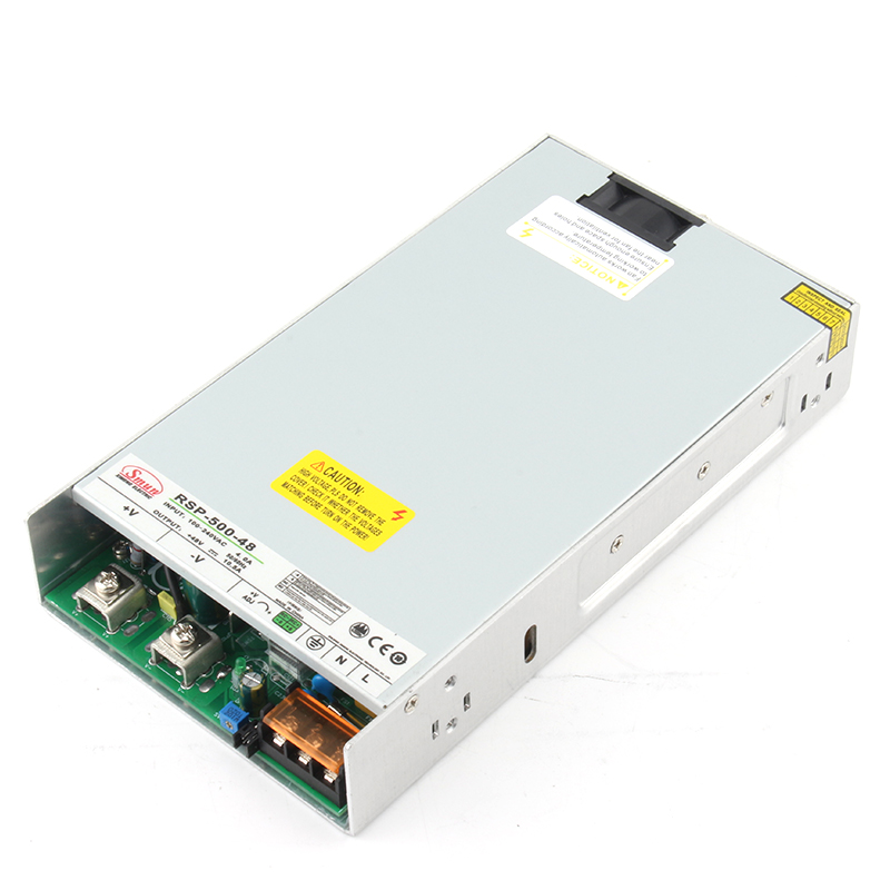
Active solutions deliver outstanding performance. They routinely achieve a PF greater than 0.95, effectively eliminating harmonic distortion. The circuitry is lightweight and compact. Active PFC also automatically supports universal input voltages (90VAC to 264VAC). The main downside involves the generation of high-frequency noise (EMI), which requires careful subsequent filtering. This approach is absolutely mandatory for high-draw applications. For instance, a modern 500W medical switching power supply exclusively relies on Active PFC to meet strict size, weight, and efficiency mandates.
Comparison Chart: Active vs. Passive PFC in Medical Applications
| Feature | Passive PFC | Active PFC |
|---|---|---|
| Mechanism | Inductive and capacitive line filters | High-frequency switching boost converter |
| Typical Power Factor | 0.70 to 0.80 | 0.95 to 0.99 |
| Size & Weight | Bulky and heavy (large iron-core chokes) | Compact and lightweight |
| EMI Generation | Virtually none | High (Requires specialized filtering) |
| Input Voltage Range | Fixed or narrow range (requires switching) | Universal (90VAC - 264VAC) |
| Best Use Case | Low-power desktop monitors (<75W) | High-power surgical tools, imaging equipment |
The addition of an active PFC stage inevitably impacts overall system efficiency. Because the power must pass through an additional switching circuit before reaching the main DC-DC converter, you introduce a new point of energy loss. Evaluating how well a unit manages this loss is crucial.
When selecting a high-power PFC medical power supply, pay close attention to the underlying topology. Look specifically for LLC resonant converters paired with the PFC stage. LLC topologies enable Zero Voltage Switching (ZVS). ZVS drastically minimizes switching losses across the transistors. This reduction directly lowers the thermal load. Less heat generation proves especially critical in fanless or completely enclosed medical devices, where active cooling is prohibited due to contamination risks.
Medical power supply design involves a constant engineering tension between suppressing noise and maintaining patient safety. This dynamic requires strict attention during the evaluation phase.
Hospital grid voltages vary significantly around the world. Even within a single facility, voltage sags frequently occur when heavy machinery powers on. You must verify that the active PFC circuit maintains high efficiency across global hospital voltage fluctuations.
A robust supply will operate flawlessly from 90VAC up to 264VAC without requiring manual intervention. Check the efficiency curves provided by the manufacturer. Poorly designed PFC stages suffer massive efficiency drops at the lower end of the voltage spectrum (e.g., 90VAC). This drop results in sudden heat spikes, which can trigger thermal shutdown mechanisms during critical medical procedures.
Even the most impressive specification sheet cannot guarantee seamless integration. When embedding these power supplies into a mechanical chassis, several practical risks emerge. Engineering teams must anticipate these challenges early in the design cycle.
Selecting a vendor based entirely on marketing brochures invites disaster. Many suppliers claim their units are "medical grade" or feature "advanced PFC." You must reject vendors who provide only generic claims. Demand comprehensive CB test reports and official EMI test plots. Review these plots to ensure the power supply demonstrates a comfortable margin below the standard emission limits. A unit hovering exactly on the limit line frequently fails integration testing once placed inside your specific metal or plastic chassis.
The active PFC circuit represents a highly stressed section of the power supply. Component pedigree matters immensely. Evaluate the origin and quality of the primary PFC bulk capacitor. This specific capacitor handles high ripple currents and is a common point of failure. Industry best practice demands the use of premium, 105°C-rated capacitors from reputable manufacturers (e.g., top-tier Japanese brands). A cheaper 85°C capacitor will drastically reduce the Mean Time Between Failures (MTBF) of the entire medical device.
Determine early if your application requires a modified standard unit. Standard off-the-shelf units work perfectly for benign environments. However, medical devices frequently face harsh cleaning chemicals, high humidity, or unique physical space constraints. Assess whether the vendor can apply specialized conformal coating to the PCB to protect the sensitive PFC control circuits from moisture. Furthermore, verify the vendor's local engineering support capabilities. Seamless communication with their design team accelerates the modification process.
Moving from the research phase to active testing requires a systematic approach. First, request physical evaluation samples of the targeted power supplies. Do not rely solely on digital models. Next, demand full MTBF documentation, ensuring they calculated the data using recognized standards like MIL-HDBK-217F or Telcordia. Finally, initiate thermal and EMI pre-compliance testing immediately. Conduct these tests with the power supply mounted inside your actual device chassis, running your maximum continuous software load.
Specifying PFC in a medical context is never a simple box-ticking exercise. It stands as a critical system-level decision that directly impacts thermal design, EMI compliance, and ultimate patient safety. Navigating the rigid standards of IEC 61000-3-2 and IEC 60601-1 requires balancing the harmonic benefits of active PFC against the strict limits on leakage current. Engineers must look beyond basic wattage to evaluate advanced topologies, derating curves, and component pedigree.
For demanding clinical applications, selecting a validated, high-efficiency unit minimizes regulatory friction and significantly accelerates your time-to-market. By prioritizing low EMI emissions, optimal hold-up times, and zero-voltage switching architectures, you ensure your device operates flawlessly in chaotic hospital grids. We encourage you to consult with an application engineer today. Request detailed specification sheets for standard medical power supplies to perfectly match your precise power load and regulatory compliance requirements.
A: Generally, regulatory standards mandate harmonic current emission mitigation (and thus PFC) for power supplies drawing more than 75W. Devices drawing less than this threshold often bypass strict IEC 61000-3-2 harmonic limits, though individual regional regulations may vary slightly.
A: Indirectly, yes. The high-frequency switching of Active PFC requires EMI filtering. Standard filtering uses Y-capacitors which increase leakage current. Medical-grade supplies are specifically engineered to mitigate this EMI without exceeding safe leakage thresholds.
A: LLC resonant converters enable zero-voltage switching (ZVS), which drastically reduces the switching losses introduced by the active PFC stage. This is crucial for maintaining high efficiency and minimizing heat in devices like a 500W medical switching power supply.