
- All
- Product Name
- Product Keyword
- Product Model
- Product Summary
- Product Description
- Multi Field Search
Views: 0 Author: Site Editor Publish Time: 2026-10-18 Origin: Site


Choosing a power supply for telecom, networking or transportation equipment means specifying for continuity of service rather than for a duty cycle: the load never switches off, the input is rarely clean, and the unit is frequently sealed in a cabinet nobody opens for years. That changes the priority order. Input range and hold-up time come before efficiency, redundancy topology comes before chassis format, and derating at the real internal ambient decides the wattage far more often than the nameplate rating does. This guide sets out the requirements these three application families actually impose, then walks through the dimensions that decide which part number you request a quotation for.
Continuity of service is the design goal. These loads run continuously, so availability — not peak efficiency — drives the specification.
Input range is the first filter. Telecom DC plants, vehicle systems and industrial mains all present different windows; a supply that fits one rarely fits another.
Hold-up time is a requirement, not a bonus. It must cover the time your load needs before it can shut down safely, measured at the real load.
Redundancy is a separate component. 1+1 and N+1 are achieved with a redundancy module, not by paralleling supplies alone.
Derate at the sealed-cabinet ambient. The internal temperature, not the room temperature, sets the usable output.
Confirm compliance from the supplier's own declaration. Standards apply to the end equipment, and their scope must be verified rather than assumed.
A telecom rack, an aggregation switch or a signalling cabinet runs 24 hours a day, so every hour of downtime is a service event rather than a scheduling inconvenience. That shifts the emphasis from conversion efficiency to thermal margin, protection behaviour and the ability to keep operating through an input disturbance. Protection thresholds matter more than the efficiency curve: a supply that trips on a brief input sag has failed the application even if its nameplate efficiency is excellent. The mechanisms behind that relationship are covered in our guide to how switching power supply improves system reliability.
Wider than the nominal figure suggests. A 48V telecom DC plant holds close to 48V but not exactly, and a 24V industrial bus rises during charging and sags under load. In transportation the source may be a battery whose terminal voltage moves substantially across the charge and discharge cycle. Write down the minimum and maximum your system can present, then select against that window with margin — a supply specified only at the nominal voltage will drop out at the least convenient moment.
Because the supply is the first component the disturbance reaches. Published specifications in this portfolio place surge current at 20A at 115 VAC and 40A at 230 VAC, with inrush behaviour that must be tolerated by the upstream protection. Wider input tolerance and a PFC front end both help: the 1000W adjustable PFC supply for telecom publishes an input range of 110–240 VAC at 47–63 Hz, a maximum output power of 1008W, an output current range of 6.7A to 42A across a 24V–150V adjustment window, conversion efficiency of 88.3% to 91%, and an MTBF of at least 720,600 hours. On the DC side the same logic applies: a step-down converter feeding a telecom rail must survive the transients present on the bus without transferring them to the load.
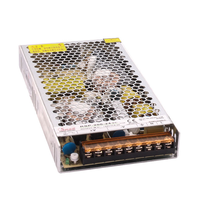
Hold-up time is the interval the supply maintains its output after the input is removed, quoted at a defined load. One published example specifies hold-up time of 60 ms at 230 VAC and 12 ms at 115 VAC at full load. The number that matters is how long your load needs to complete a safe shutdown or to hand over to a redundant feed — not the largest figure available on a datasheet. Measure or calculate that requirement first, then compare it against the published figure at your actual load, since hold-up shortens as loading increases.
1+1 uses two supplies sized so that either one can carry the full load, giving protection against a single failure with simple wiring. N+1 uses N supplies for the load plus one spare, which is the usual choice when the load is distributed across several converters or when the system must tolerate one failure without interruption in a larger installation. Both require a redundancy module to decouple the outputs: a dedicated 20A DIN-rail module operating from 12V, 24V or 48V DC supports 1+1 and N+1 configurations. Two supplies wired in parallel without that decoupling do not provide the isolation the topology assumes.
Read the derating curve at the internal ambient, then check whether the curve is quoted with or without forced airflow. A published example in this portfolio states an operating temperature of −25 °C to +50 °C with derating above 50 °C, which tells you the figure is not a working limit but a curve to be read. In a sealed outdoor cabinet the internal ambient may sit well above the outside air, so the correct input to the calculation is the measured cabinet temperature at the mounting position. For racked cabinet builds the DIN rail power supplies for cabinet builds follow the same logic and frequently form the DC distribution layer.
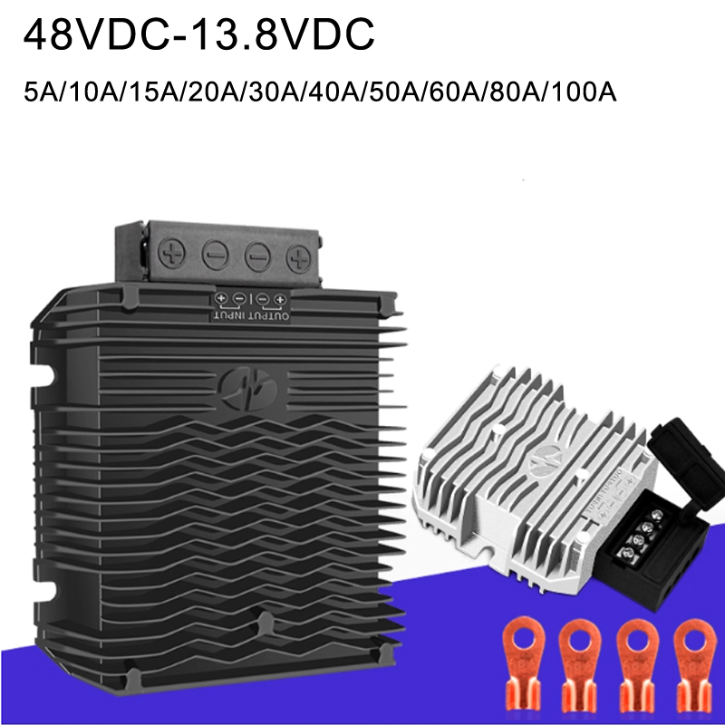
Isolation requirements follow from the grounding arrangement of the equipment, not from a preference. Where the load must not share a reference with the source, an isolated converter is required; where the rack already provides a common reference, a non-isolated converter is the economical choice and the savings can go into enclosure protection instead — a 48V to 13.8V telecom DC-DC converter is the standard pattern for that duty. On the EMI side, a supply with power factor correction presents a lower harmonic current profile, which simplifies the argument at the end-equipment level, and the telecom and industrial grade power supplies in this portfolio cover both AC-input and DC-input arrangements.
For unattended sites the answer is the functions that let a remote operator distinguish a supply fault from a load fault. Published protection sets in this portfolio include short circuit, overload, overvoltage, overtemperature, fan failure and undervoltage, and a fan-failure or undervoltage flag is what tells you whether the unit is degrading or has failed outright. Decide which of those signals your monitoring system can consume before you finalise the part number.
Standards apply to the end equipment rather than to the supply in isolation, so the compliance question starts with your product's category — for example IEC/EN 62368-1 for information and communication technology equipment, or the medical standard IEC/EN 60601-1 where applicable, which adds leakage current constraints. Harmonic current emissions for equipment connected to the public low-voltage supply fall under IEC 61000-3-2. In every case, ask the supplier for their own declaration and keep it with the project file rather than inferring compliance from a datasheet summary.
Table 1: Requirement profile by application
Requirement | Telecom | Networking | Transportation |
|---|---|---|---|
Typical supply voltage | 48V DC plant; wide-range AC input | 12V / 24V / 48V DC; AC mains | Battery bus, frequently 12V / 24V / 48V / 72V |
Tolerable interruption | Very short; redundancy expected | Short; redundancy common in core sites | Must ride through engine and traction events |
Redundancy requirement | 1+1 or N+1 | 1+1 for core equipment | Dependent on function criticality |
Ambient temperature | Enclosed cabinet, moderate to high | Equipment room, moderate | Wide range, vibration present |
Typical power band | 200W to 1000W per unit | 200W to 3000W per rack feed | 100W to 2000W |
Dominant selection risk | Hold-up time and redundancy | Derating in sealed cabinets | Input range and transient tolerance |
Table 2: Product and rating coverage
Product family | Published rating | Published output | Notable published detail |
|---|---|---|---|
RSP-200 Series | 200W / 204W | 12V, 24V, 27.3V | Input 88–264 VAC or 124–370 VDC; power factor above 0.95 at 230 VAC |
RSP-320 | 320.4W / 321W / 321.6W | 12V, 15V, 24V | Input 88–264 VAC or 124–370 VDC; leakage below 1.5 mA at 240 VAC |
Adjustable PFC supply, telecom | 1008W maximum | 24V–150V adjustable in 2V steps | Input 110–240 VAC; efficiency 88.3%–91%; MTBF at least 720,600 hours |
RSP-2000 | 2000W constant | 24V–150V adjustable, ±3% | Power factor at least 0.99; 280 × 140 × 65 mm; −25 °C to +50 °C |
RSP-3000 | 3000W at 220 VAC, 2200W at 110 VAC | Adjustable, model dependent | Input 100–264 VAC; efficiency up to 93.4% |
Figures above are quoted from published series designations and specification tables. Confirm the exact model, input window and derating curve on the datasheet before ordering.
Consider a 48V telecom rack feed that must survive a single supply failure without dropping the load, where the load needs 15 ms to complete a controlled shutdown and draws 20A at 48V.
Step 1 — Convert the load to power. At 48V and 20A the load is 960W.
Step 2 — Establish the input window. Confirm the minimum and maximum the DC plant can present, then select a supply whose published input range covers both ends with margin.
Step 3 — Compare hold-up time against the requirement. Published hold-up is quoted at full load and at a specific input voltage, and it shortens at higher loading. If the published figure at your load does not cover the 15 ms the load requires, either accept a slightly larger supply or add capacitance at the load — but size the margin from the datasheet, not from the headline number.
Step 4 — Choose the redundancy topology. With a single load requiring uninterrupted operation, 1+1 with each supply rated for the full 960W is the straightforward answer; N+1 becomes relevant when the load is split across several feeds.
Step 5 — Add the decoupling component. Specify a redundancy module rated above the 20A per supply, and confirm its published voltage drop and efficiency at your load so that the drop does not consume the margin you calculated in step 3.
Illustrative method only; not a SMUN product specification.
Input window — minimum and maximum the source can present, with margin.
Internal ambient — measured inside the closed cabinet at the mounting position.
Load profile — continuous current, inrush, and how long the load needs on loss of input.
Redundancy topology — 1+1, N+1, or none, plus the decoupling module rating.
Monitoring signals — which fault flags your system can consume.
Compliance scope — the standard governing your end equipment, and the supplier declaration you need.
Telecom, networking and transportation power supplies are selected for availability, and availability is built from four decisions in a fixed order: the input window the source presents, the hold-up time the load requires, the redundancy topology the service level demands, and the thermal margin the installed ambient leaves. Efficiency and cost follow those decisions rather than leading them.
The most common specification error in this category is treating the nameplate rating as an available output. A 2000W unit rated to +50 °C in a sealed outdoor cabinet is not a 2000W unit at the internal ambient that cabinet reaches. Reading the derating curve at the measured temperature is what converts a nameplate into a deliverable figure.
Before requesting a quotation, confirm the input window, the internal ambient, the hold-up requirement and whether a redundancy module is in scope. Answer those four and the shortlist is usually two or three part numbers long.
A: Enough to cover whatever your load must complete after the input is lost — a controlled shutdown, a handover to a redundant feed, or a ride-through of a short disturbance. Compare the published figure at your actual load and input voltage, because hold-up shortens as loading rises.
A: Not by wiring the outputs together directly. Redundancy requires decoupling so that a failed unit cannot pull the shared rail down; a dedicated redundancy module rated above the per-supply current provides that function for 1+1 and N+1 configurations.
A: No. The rating is quoted at a defined ambient and load condition, and the achievable output falls as the internal temperature rises. In a sealed cabinet, the derating curve at the measured internal ambient — not the nameplate figure — determines what the unit can deliver.
A: Applicability depends on the equipment class, the input current and the edition of the harmonic current limits governing your product; IEC 61000-3-2 addresses harmonic current emissions for equipment connected to the public low-voltage supply. A PFC front end is a common route to satisfying those limits, and it also lowers input current at the same output power.
A: The ones that let a remote operator separate a supply fault from a load fault. Published protection sets in this portfolio include short circuit, overload, overvoltage, overtemperature, fan failure and undervoltage, and the fan-failure and undervoltage flags are usually the most useful for unattended sites.