Ένα τροφοδοτικό ανοιχτού πλαισίου είναι ένα γυμνό συγκρότημα PCB με εκτεθειμένα εξαρτήματα και βιδωτούς ακροδέκτες, ενώ ένα κλειστό τροφοδοτικό τοποθετεί το ίδιο κύκλωμα μετατροπής μέσα σε ένα μεταλλικό ή διάτρητο κάλυμμα. Η επιλογή μεταξύ τους δεν έχει να κάνει με το ποιο αποδίδει καλύτερα — είναι το ποιο μπορεί να δεχτεί το περίβλημά σας, η πρακτική καλωδίωσης και ο έλεγχος ασφαλείας σας. Εάν ο εξοπλισμός σας διαθέτει ήδη ένα μεταλλικό ντουλάπι προσβάσιμο από εργαλεία με σωστές αποστάσεις ερπυσμού και ροή αέρα, μια μονάδα ανοιχτού πλαισίου σας προσφέρει περισσότερη ισχύ ανά δολάριο και μεγαλύτερη ελευθερία σχεδίασης. Εάν η προμήθεια είναι προσβάσιμη από τον πελάτη, εγκατασταθεί σε συνεργείο με σκόνη ή αποστέλλεται ως αυτόνομο κουτί, μια κλειστή μονάδα κοστίζει περισσότερο, αλλά αφαιρεί μια ολόκληρη κατηγορία έγκρισης και κίνδυνο αστοχίας πεδίου. Αυτός ο οδηγός συγκρίνει τις δύο μορφές σχετικά με τις διαστάσεις που καθορίζουν πραγματικά μια κατασκευή.
Βασικά Takeaways
Το περίβλημα που έχετε ήδη καθορίζει τη μορφή. Μια μονάδα ανοιχτού πλαισίου δανείζεται προστασία από το ντουλάπι υποδοχής. μια κλειστή μονάδα φέρνει τη δική της.
Ο ερπυσμός και το διάκενο είναι απαίτηση συναρμολόγησης, όχι εξαρτήματος. Οι εκτεθειμένοι ακροδέκτες πρέπει να ικανοποιούν τις αποστάσεις που απαιτούνται από τα ισχύοντα πρότυπα ασφαλείας μόλις εγκατασταθούν.
Τα κλειστά περιβλήματα ανταλλάσσουν το θερμικό κεφάλι για προστασία. Το κάλυμμα που κρατά τη σκόνη έξω διατηρεί επίσης τη θερμότητα, επομένως η καμπύλη μείωσης έχει μεγαλύτερη σημασία.
Το PFC αλλάζει το προφίλ ρεύματος εισόδου, όχι μόνο το ποσοστό απόδοσης. Τα όρια αρμονικού ρεύματος ισχύουν για τον τελικό εξοπλισμό και ένα μπροστινό άκρο PFC συχνά απλοποιεί τη συμμόρφωση.
Σχεδιάστε τη διαδρομή πιστοποίησης προτού διορθώσετε τη μορφή. Το ισχύον πρότυπο, το περίβλημα και η μέθοδος καλωδίωσης αποφασίζονται από κοινού.
Αντιστοιχίστε τη μορφή με το μοντέλο συντήρησης. Οι μονάδες με δυνατότητα αντικατάστασης πεδίου προτιμούν τις κλειστές μονάδες. Τα εργοστασιακά ενσωματωμένα συγκροτήματα ευνοούν το ανοιχτό πλαίσιο.
Τι μετράει ως τροφοδοτικό ανοιχτού πλαισίου
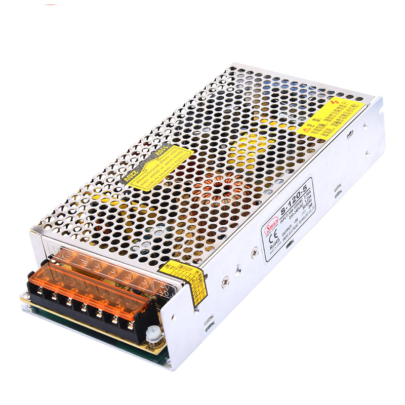
Μια τροφοδοσία ανοιχτού πλαισίου παρέχεται ως γεμάτη πλακέτα με βάση στήριξης και μπλοκ ακροδεκτών, χωρίς κάλυμμα στα ηλεκτροφόρα μέρη. Το δημοσιευμένο Η σειρά τροφοδοσίας ανοιχτού πλαισίου βρίσκεται στην κορυφή της σκάλας ισχύος, όπου είναι συνηθισμένα τα συγκροτήματα που τοποθετούνται στο πλαίσιο.
Γιατί εξακολουθεί να χρησιμοποιείται η μορφή ανοιχτού πλαισίου;
Επειδή αφαιρεί τα πάντα μεταξύ της πηγής θερμότητας και του αέρα του περιβάλλοντος. Δεν υπάρχει κάλυμμα που να εμποδίζει τη μεταφορά, κανένα σχέδιο διάτρησης για το σχεδιασμό και κανένα πρόσθετο μέταλλο στην πηγή. Για ένα προϊόν ενσωματωμένο στο πλαίσιο, το ντουλάπι υποδοχής παρέχει ήδη το φράγμα, τη διαδρομή ροής αέρα και τη δομή στερέωσης, επομένως ένα δεύτερο περίβλημα προσθέτει κόστος, όγκο και θερμική αντίσταση χωρίς να προσθέτει προστασία που μπορεί να αντιληφθεί ο χρήστης.
Ποιες υποχρεώσεις μεταφέρει η μορφή ανοιχτού πλαισίου στον σχεδιαστή;
Ο σχεδιαστής κληρονομεί τις χωρικές αποστάσεις, την ερώτηση για την ασφάλεια των δακτύλων και την πειθαρχία της καλωδίωσης. Οι βιδωτές ακροδέκτες είναι εκτεθειμένοι, επομένως το συγκρότημα πρέπει να είναι διατεταγμένο έτσι ώστε ένα εργαλείο ή ένα δάχτυλο να μην μπορεί να φτάσει σε έναν αγωγό υπό τάση σε κανονική λειτουργία. Τα εξαρτήματα που παράγουν θερμότητα κάθονται απευθείας στη ροή αέρα, κάτι που αποτελεί πλεονέκτημα μόνο εάν αυτή η ροή αέρα έχει πράγματι καθοριστεί.
Τι μετράει ως κλειστό τροφοδοτικό
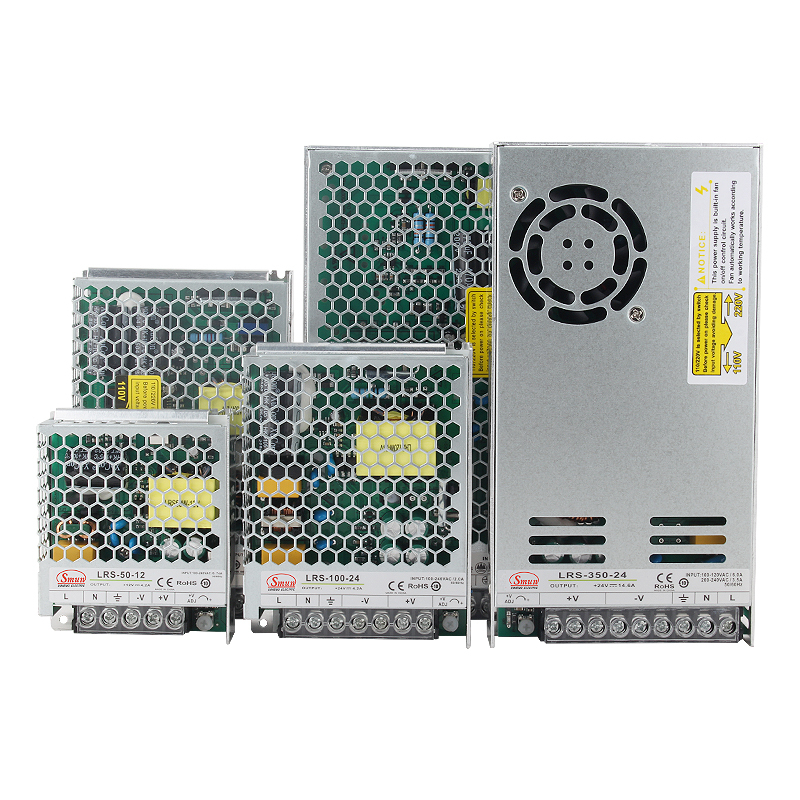
Ένα κλειστό τροφοδοτικό τυλίγει το στάδιο μετατροπής σε μια μεταλλική θήκη, συχνά διάτρητη για μεταφορά. Το δημοσιευμένο Τα τροφοδοτικά κλειστού τύπου περιλαμβάνουν λεπτές μορφές χαμηλού προφίλ σχεδιασμένες για σφιχτά πάνελ και μορφές πλαισίου υψηλότερης ισχύος με εσωτερικό ανεμιστήρα.
Γιατί το κάλυμμα αλλάζει τόσο πολύ το επιχείρημα ασφάλειας;
Επειδή το φράγμα ανήκει πλέον στο εξάρτημα παρά στο συγκρότημα. Ο χρήστης δεν μπορεί να αγγίξει ένα ενεργό μέρος μέσα από μια κλειστή θήκη, επομένως η ερώτηση ερπυσμού σε επίπεδο συναρμολόγησης περιορίζεται στις καταχωρήσεις καλωδίωσης εισόδου και εξόδου. Αυτός είναι ο μόνος μεγαλύτερος λόγος που οι κλειστές μονάδες κυριαρχούν στα προϊόντα που εγκαθίστανται στο πεδίο από τελικούς χρήστες και όχι από εκπαιδευμένο κατασκευαστή πινάκων.
Ποιες εφαρμογές οδηγούν την εσώκλειστη μορφή;
Κατασκευαστές πάνελ που πρέπει να τοποθετήσουν ένα απόθεμα σε ένα ρηχό ερμάριο DIN-rail, κατασκευαστές μηχανημάτων που αποστέλλουν ένα σφραγισμένο κιβώτιο ελέγχου και οποιοδήποτε προϊόν όπου η προμήθεια είναι ορατή στον τελικό χρήστη. Μια λεπτή κλειστή μορφή όπως το Το λεπτό κλειστό PSU της σειράς LRS 35W–600W υπάρχει ακριβώς για να συνδυάζει την προστασία μιας θήκης με τα όρια βάθους ενός σύγχρονου πίνακα ελέγχου.
Αξιολόγηση σε επίπεδο εξαρτήματος συν καταχωρίσεις καλωδίωσης
Μοντέλο συντήρησης
Ενσωματωμένη αντικατάσταση στο εργοστάσιο
Μονάδα με δυνατότητα αντικατάστασης πεδίου
Τυπική εφαρμογή
Εξοπλισμός OEM ενσωματωμένος στο πλαίσιο
Κατασκευές πάνελ, αυτόνομα προϊόντα και προϊόντα που εξυπηρετούνται στο πεδίο
Σχετικό κόστος σε ίση ισχύ
Χαμηλότερος
Πιο ψηλά
Επιλογές ψύξης
Φυσική μεταφορά ή εξαναγκασμένος αέρας
Φυσική μεταφορά; ανεμιστήρα σε μορφές υψηλής ισχύος
Μηχανικοί και Ασφαλείς Περιορισμοί
Πώς ισχύουν οι κανόνες ερπυσμού και εκκαθάρισης μετά την εγκατάσταση της μονάδας;
Ο ερπυσμός είναι η απόσταση κατά μήκος μιας επιφάνειας μεταξύ δύο αγώγιμων τμημάτων. Η απόσταση είναι η απόσταση μέσω του αέρα. Και τα δύο μετρώνται στο συγκρότημα όπως έχουν εγκατασταθεί, όχι στον γυμνό πίνακα. Μια τροφοδοσία ανοιχτού πλαισίου που φαίνεται συμβατή στον πάγκο μπορεί να αποτύχει όταν η καλωδίωση εισέλθει στους ακροδέκτες υπό γωνία, επομένως δρομολογήστε τους αγωγούς έτσι ώστε ένας χαλαρός κλώνος ή ένα ολισθηρό καλώδιο να μην μπορεί να γεφυρώσει το πρωτεύον και το δευτερεύον.
Τι κάνει ένα μπλοκ ακροδεκτών ασφαλές για τα δάχτυλα;
Ένα τερματικό που είναι ασφαλές για τα δάχτυλα είναι αυτό του οποίου τα ενεργά μέρη δεν μπορούν να έλθουν σε επαφή με ένα τυπικό δάκτυλο δοκιμής στην εγκατεστημένη θέση. Οι χωνευτές βίδες, τα αρθρωτά καλύμματα και οι πλάκες καλύμματος το επιτυγχάνουν αυτό. εκτεθειμένες κεφαλές βιδών όχι. Όπου η μορφή είναι ανοιχτό πλαίσιο, το περιβάλλον ντουλάπι ή ένα πρόσθετο κάλυμμα τερματικού πληροί την απαίτηση.
Πότε χρειάζεστε εξαναγκασμένη ροή αέρα αντί για μεταφορά;
Η εξαναγκασμένη ροή αέρα απαιτείται όταν το περιβάλλον μέσα στο ερμάριο υπερβαίνει αυτό που μπορεί να απορρίψει η διαδρομή μεταφοράς στο απαιτούμενο φορτίο. Διαβάστε την καμπύλη μείωσης στον πραγματικό εσωτερικό προσανατολισμό περιβάλλοντος και τοποθέτησης και, στη συνέχεια, αποφασίστε εάν ένας ανεμιστήρας είναι φθηνότερος από μια μεγαλύτερη παροχή. Ένας ανεμιστήρας φέρνει επίσης ένα κινούμενο εξάρτημα, μια διαδρομή σκόνης και ένα αντικείμενο συντήρησης, οπότε πάρτε το μια σκόπιμη απόφαση.
Τι αλλάζει όταν τοποθετείτε την παροχή μέσα σε ένα μεταλλικό πλαίσιο;
Το πλαίσιο γίνεται μέρος της θερμικής διαδρομής και, σε κάποιο βαθμό, της δομής EMI. Αυτό είναι συνήθως ευνοϊκό, αλλά αυξάνεται και η θερμοκρασία του πλαισίου. Η συγκόλληση του πλαισίου στο πλαίσιο είναι συνήθης πρακτική. επαληθεύστε την επίδραση στα κοντινά εξαρτήματα αντί να υποθέσετε ότι το μέταλλο απομακρύνει τη θερμότητα.
Η διαδρομή πιστοποίησης που πρέπει να σχεδιάσετε
Ποιο πρότυπο ασφάλειας ισχύει για το τελικό προϊόν σας;
Το ισχύον πρότυπο ακολουθεί το τελικό προϊόν και όχι το τροφοδοτικό. Το IEC/EN 62368-1 καλύπτει τον εξοπλισμό ήχου/εικόνας, τεχνολογίας πληροφοριών και επικοινωνιών και έχει αντικαταστήσει σε μεγάλο βαθμό τα παλαιότερα 60950-1 και 60065 για αυτήν την οικογένεια. Το IEC/EN 60601-1 ισχύει για ιατρικό ηλεκτρικό εξοπλισμό και προσθέτει απαιτήσεις όπως όρια ρεύματος διαρροής που περιορίζουν την επιλογή τροφοδοσίας. Διαβάστε το πρότυπο που διέπει το τελικό προϊόν σας και, στη συνέχεια, επιλέξτε τη μορφή που επιτρέπει στη συναρμολόγηση να το ικανοποιήσει — και λάβετε τη δήλωση του ίδιου του προμηθευτή αντί να υποθέσετε τη συμμόρφωση από μια περίληψη του φύλλου δεδομένων.
Τα αρμονικά όρια ρεύματος επηρεάζουν την απόφαση μορφής;
Το IEC 61000-3-2 θέτει όρια στις εκπομπές αρμονικών ρευμάτων για εξοπλισμό συνδεδεμένο στη δημόσια παροχή χαμηλής τάσης, με δυνατότητα εφαρμογής ανάλογα με την κατηγορία εξοπλισμού και το ρεύμα εισόδου. Επειδή αυτά τα όρια ισχύουν για τον τελικό εξοπλισμό και όχι για μια μονάδα μεμονωμένα, μια παροχή με διόρθωση συντελεστή ισχύος στο μπροστινό άκρο απλοποιεί σημαντικά το επιχείρημα. Επιβεβαιώστε την ισχύουσα έκδοση και το πεδίο εφαρμογής με τον συνεργάτη συμμόρφωσης.
Τι πραγματικά σας αγοράζει το PFC στον λογαριασμό των υλικών;
Ένα μπροστινό άκρο διορθωμένο με συντελεστή ισχύος αντλεί ρεύμα σε σχήμα πιο κοντά στην κυματομορφή της τάσης τροφοδοσίας, γεγονός που αυξάνει τον συντελεστή ισχύος και μειώνει το αρμονικό περιεχόμενο. Τα δημοσιευμένα στοιχεία απεικονίζουν τη διαφορά: το Το τροφοδοτικό RSP-320 320W PFC καθορίζεται με συντελεστή ισχύος μεγαλύτερο από 0,95 στα 230 VAC και μεγαλύτερο από 0,98 στα 115 VAC πλήρες φορτίο, ρεύμα εισόδου 4Α στα 115 VAC και 2Α στα 230 VAC, ρεύμα υπέρτασης 20Α και 40Α αντίστοιχα, ανάλογα με την ισχύ 08Α μοντέλο και ρεύμα διαρροής κάτω από 1,5 mA στα 240 VAC. Η συναλλαγή είναι υψηλότερος αριθμός συστατικών και τιμή μονάδας έναντι μιας απλούστερης διαδρομής συμμόρφωσης.
Πίνακας 2: Εύρος ισχύος και εξόδου διαθέσιμα σε όλες τις σειρές
Σειρά
Δημοσιευμένη ισχύς
Δημοσιευμένες τάσεις εξόδου
Μορφοποίηση σημείωσης
Σειρά S
15W έως 1200W (ονομασία σειράς). μοντέλο φύλλου δεδομένων S-25 έως S-600
Οι παραπάνω σειρές σειρών παρατίθενται από τους δημοσιευμένους πίνακες ονομασιών και προδιαγραφών προϊόντων. Επιβεβαιώστε το ακριβές μοντέλο, το εύρος εισαγωγής και το παράθυρο προσαρμογής στο φύλλο δεδομένων πριν την παραγγελία.
Υπολογισμός απομείωσης και θερμικού χώρου κεφαλής
Ο Η σειρά τροφοδοτικών μεταγωγής AC/DC εκτείνεται σε ένα αρκετά μεγάλο εύρος ισχύος που η επιλογή μορφής και ο θερμικός χώρος κεφαλής αλληλεπιδρούν άμεσα. Σκεφτείτε ένα πάνελ που χρειάζεται 200W συνεχούς ισχύος.
Βήμα 1 — Δημιουργήστε το εσωτερικό περιβάλλον. Μετρήστε τη θερμοκρασία του αέρα μέσα στο κλειστό περίβλημα στη θέση τοποθέτησης, όχι τη θερμοκρασία δωματίου. Υποθέστε για αυτό το παράδειγμα 50 °C.
Βήμα 2 — Πάρτε την απαίτηση φορτίου. Το φορτίο αντλεί συνεχώς 200W. Σε μια μονάδα ονομαστικής ισχύος 200 W που είναι φορτίο 100% χωρίς περιθώριο — αποδεκτό μόνο εάν η καμπύλη μείωσης το επιτρέπει στους 50 °C.
Βήμα 3 — Διαβάστε την καμπύλη μείωσης στο πραγματικό περιβάλλον. Οι καμπύλες του κατασκευαστή επιτρέπουν συνήθως την πλήρη ονομαστική ισχύ σε μια καθορισμένη θερμοκρασία και τη μειώνουν πάνω από αυτό το σημείο. Εάν η καμπύλη επιτρέπει την πλήρη ισχύ μόνο στους 45 °C και μειώνεται πάνω από αυτήν, μια μονάδα 200W δεν αποδίδει 200W στους 50 °C. Επιλέξτε υψηλότερη βαθμολογία ή βελτιώστε τη ροή αέρα.
Βήμα 4 — Ελέγξτε το εφέ του περιβλήματος. Μια κλειστή μονάδα προσθέτει θερμική αντίσταση μεταξύ των εξαρτημάτων και του αέρα του ντουλαπιού. Συγκρίνετε τις καμπύλες μείωσης του ανοιχτού πλαισίου και των εσωκλειόμενων υποψηφίων στο ίδιο περιβάλλον αντί να υποθέσετε ότι είναι ίσες.
Βήμα 5 — Αποφασίστε μεταξύ περισσότερων Watt και περισσότερης ροής αέρα. Η φθηνότερη διαδρομή σε κόστος μονάδας είναι συνήθως η αύξηση της ισχύος. η φθηνότερη διαδρομή σε όγκο περιβλήματος είναι συνήθως η βελτίωση της διαδρομής ροής αέρα. Και τα δύο πρέπει να αξιολογηθούν με βάση την καμπύλη μείωσης.
Μόνο ενδεικτική μέθοδος. δεν είναι προδιαγραφή προϊόντος SMUN.
Ροή εργασιών επιλογής: Πέντε ερωτήσεις πριν ζητήσετε προσφορά
Ποιος μπορεί να αγγίξει την παροχή σε υπηρεσία; Εάν κάποιος άλλος εκτός από εκπαιδευμένο πρόγραμμα δημιουργίας πάνελ, ξεκινήστε με μια εσώκλειστη μορφή.
Ποιο είναι το εσωτερικό περιβάλλον στη θέση τοποθέτησης; Αυτός ο αριθμός, όχι η θερμοκρασία δωματίου, επιλέγει την ισχύ.
Ποιος είναι ο βαθύτερος διαθέσιμος χώρος; Οι μορφές λεπτού κλειστού και ανοιχτού πλαισίου διαφέρουν σημαντικά ως προς το βάθος τοποθέτησης.
Ποιο πρότυπο διέπει το τελικό προϊόν; Αυτό το πρότυπο, όχι μια προτίμηση, αποφασίζει τις απαιτήσεις διαρροής και απόστασης.
Πώς θα αντικατασταθεί η μονάδα; Η αντικατάσταση πεδίου ευνοεί μια κλειστή μονάδα. η εργοστασιακή ενσωμάτωση ευνοεί το ανοιχτό πλαίσιο.
Απαντήστε σε αυτές τις πέντε και η σύντομη λίστα συνήθως συμπτύσσεται σε δύο ή τρεις σειρές.
Σύναψη
Το ανοιχτό πλαίσιο και τα κλειστά τροφοδοτικά δεν είναι ανταγωνιστικά προϊόντα — είναι δύο φιλοσοφίες τοποθέτησης για το ίδιο κύκλωμα μετατροπής. Το ανοιχτό πλαίσιο κερδίζει όταν το ντουλάπι υποδοχής τροφοδοτεί ήδη το φράγμα, τη ροή αέρα και τη δομή στήριξης και όταν το συγκρότημα κατασκευάζεται από έναν εκπαιδευμένο ολοκληρωτή. Το εσώκλειστο κερδίζει κάθε φορά που η προμήθεια πρέπει να προστατευθεί, είτε επειδή μπορεί να φτάσει ο τελικός χρήστης, είτε το περιβάλλον είναι μολυσμένο είτε η μονάδα αποστέλλεται και συντηρείται ως μονάδα.
Επομένως, η απόφαση λαμβάνεται στον μηχανολογικό σχεδιασμό, όχι στις ηλεκτρικές προδιαγραφές. Διορθώστε πρώτα το εσωτερικό περιβάλλον, το διαθέσιμο βάθος, την απαίτηση ασφάλειας των δακτύλων και το ισχύον πρότυπο. ακολουθεί η ισχύς και η σειρά. Η αντιστροφή αυτής της παραγγελίας είναι ο πιο συνηθισμένος λόγος που μια επιλογή προμήθειας πρέπει να επαναληφθεί αργά σε ένα έργο.
Πριν ζητήσετε μια προσφορά, επιβεβαιώστε τρία πράγματα γραπτώς: το εσωτερικό περιβάλλον στη θέση τοποθέτησης, την καμπύλη μείωσης σε αυτό το περιβάλλον και τη δήλωση του προμηθευτή για το πρότυπο που πρέπει να πληροί το τελικό προϊόν σας.
FAQ
Ε: Μπορώ να χρησιμοποιήσω μια προμήθεια ανοιχτού πλαισίου σε εξοπλισμό που πωλείται στους τελικούς χρήστες;
Α: Μόνο εάν η διάταξη ως σύνολο εμποδίζει την επαφή με ηλεκτροφόρα μέρη και ικανοποιεί τις απαιτήσεις απόστασης του προτύπου που διέπει το τελικό προϊόν. Η μορφή ανοιχτού πλαισίου μεταφέρει αυτές τις υποχρεώσεις στο σχέδιο του περιβλήματός σας.
Ε: Μια κλειστή παροχή λειτουργεί πιο ζεστά από μια μονάδα ανοιχτού πλαισίου με την ίδια ισχύ;
Α: Το κάλυμμα προσθέτει θερμική αντίσταση μεταξύ των εξαρτημάτων και του περιβάλλοντος αέρα, επομένως η ίδια ισχύς εξόδου συνήθως σημαίνει υψηλότερη εσωτερική αύξηση της θερμοκρασίας. Συγκρίνετε τις καμπύλες μείωσης και των δύο μορφών στο πραγματικό εσωτερικό περιβάλλον σας.
Ε: Απαιτείται διόρθωση συντελεστή ισχύος για τον εξοπλισμό μου;
Α: Αυτό εξαρτάται από την κατηγορία εξοπλισμού, το ρεύμα εισόδου και την ισχύουσα έκδοση των ορίων αρμονικού ρεύματος. Το IEC 61000-3-2 διέπει τις εκπομπές αρμονικών ρευμάτων για εξοπλισμό συνδεδεμένο στη δημόσια παροχή χαμηλής τάσης. Επιβεβαιώστε το πεδίο εφαρμογής με τον συνεργάτη συμμόρφωσης. ένα μπροστινό μέρος PFC είναι μια κοινή διαδρομή για την ικανοποίηση των ορίων.
Ε: Πόσο θερμικό περιθώριο πρέπει να αφήσω;
Α: Αρκετά ώστε η καμπύλη μείωσης στο μετρημένο εσωτερικό περιβάλλον σας να εξακολουθεί να καλύπτει το φορτίο, συμπεριλαμβανομένης της ώθησης εκκίνησης και της αναμενόμενης γήρανσης. Η ανάγνωση της καμπύλης στο πραγματικό περιβάλλον, όχι η ονομαστική βαθμολογία, είναι αυτό που μετατρέπει τον υπολογισμό σε απόφαση.
Ε: Ποια μορφή ταιριάζει σε έναν πίνακα ελέγχου DIN-rail;
Α: Οι λεπτές κλειστές μορφές έχουν σχεδιαστεί για ρηχά περιβλήματα ράγας DIN και υπάρχουν αποκλειστικές σειρές ράγας DIN για κατασκευές ντουλαπιών. Οι μονάδες ανοιχτού πλαισίου χρειάζονται ένα περίβλημα υποδοχής για να παρέχει το φράγμα και τη διαδρομή ροής αέρα, κάτι που δεν προσφέρει πάντα ένα ερμάριο DIN-rail.