
- All
- Product Name
- Product Keyword
- Product Model
- Product Summary
- Product Description
- Multi Field Search
Views: 0 Author: Site Editor Publish Time: 2026-10-16 Origin: Site


A non-isolated DC-DC converter module shares a common ground between its input and its output, changing one DC voltage into another without a transformer barrier. That single decision makes these modules smaller, cheaper, and typically more efficient than isolated equivalents — and it also decides where you may use them. If your load and your source already reference the same ground, a non-isolated module is usually the better engineering and commercial choice. If they do not, it is the wrong part no matter how good its efficiency curve looks. This guide covers what "non-isolated" implies, where these modules belong, and the six specification dimensions that decide which part number you request a quote for.
Shared ground is the defining property. Input return and output return are the same node; size, cost, efficiency, and protection design follow from that.
Select by input range before output voltage. Input range is fixed by your bus; output can usually be trimmed within a published window.
Size current for the worst case, then derate. The rating at 25 °C is not what the module delivers inside a sealed enclosure at 60 °C.
Isolation is a system requirement, not a preference. An isolated module costs more and occupies more space, so settle it before comparing prices.
Sealing and vibration decide vehicle installations. Vibration, thermal cycling, and dust ingress kill modules before a single water event does.
Only the specification table counts. Confirm input range, continuous current, and protection thresholds from the datasheet, not the marketing summary.
In a non-isolated topology the input return and output return are electrically the same node. The switching stage still steps the voltage up or down, but no transformer provides galvanic separation. A published example makes this explicit: the 12V/24V to 5V non-isolated waterproof buck converter lists its isolation type as "Non-Isolated (Common Ground)", a 12V / 24V DC nominal input, a 5V DC output, 10A maximum continuous output current, conversion efficiency greater than 90%, and an operating temperature range of −40 °C to +85 °C. With no barrier there is no need for the creepage and clearance distances a transformer demands and no core losses in the power path — hence the smaller footprint, lower bill of materials, and higher efficiency at the same power level.
Three situations recur. Your source may sit at a reversed or floating reference relative to the load, which a non-isolated module cannot correct. Your load may be a measurement front end that must not be tied to the power bus — common with instrumentation amplifiers, current shunts, and isolated sensor interfaces. Or your system may need to break a ground loop where two pieces of equipment are bonded at different points.
Where any of these apply, specify an isolated module. The isolated DC-DC converter range offers a useful comparison: the SD-350 instrumentation family accepts 19–36 VDC, 36–72 VDC, or 72–144 VDC depending on model suffix, publishes a hold-up time of 30 ms at full load, and specifies withstand voltage of 1.5 KVAC input-to-output and 1.5 KVAC input-to-frame with isolation resistance of 100 MΩ at 500 VDC. That barrier is what you are paying for.
The gain is real but should not be overstated. Non-isolated buck modules in the non-isolated buck DC-DC range typically publish conversion efficiency above 90%, while an isolated converter at similar power lands slightly lower. That gap rarely decides a procurement — footprint, cost, and whether isolation is required at all are the deciding factors.
Table 1: Non-isolated vs isolated DC-DC converter modules
Dimension | Non-isolated module | Isolated module |
|---|---|---|
Input / output reference | Common ground (shared return) | Galvanically separated |
Typical conversion efficiency | Greater than 90% | Lower, due to core and copper losses |
Footprint at the same power | Smaller | Larger |
Relative cost | Lower | Higher |
Creepage and clearance demand | Reduced | Required across the barrier |
Ground-loop breaking | Not possible | Possible |
Measurement front ends | Unsuitable where a separate reference is needed | Suitable |
Typical fit | Vehicle, battery, solar, 24V / 48V bus step-down | Instrumentation and mixed-reference systems |
Vehicle electrical systems are the classic home of the non-isolated module, because the chassis is already the common reference for everything on board. The published range reflects that: 12V to 24V at 1–50A, 12V to 48V at 1–20A, 24V to 48V at 3–42A for golf cars, 36V/48V to 12V at 3–100A for electric vehicles, and 24V to 13.8V for forklifts. Boost-buck families cover inputs that may sit either side of the target, including 8–40V to 12V at 3–60A and 9–40V to 24V at 2–30A.
Higher-voltage DC buses are the second major fit. A 48V to 24V step-down converter rated 3A to 85A with an IP68 waterproof enclosure is built for solar systems, and a 72V to 12V / 13.8V family spans 5A to 60A. The telecom case is instructive: the rack already provides a common reference, so money saved on isolation goes into the enclosure rating instead.
Inside a control cabinet the 24V bus is normally the single reference for PLC modules, sensors, relays, and indicator circuits, so stepping it down to 5V or 12V is a textbook application. A 12V/24V to 5V IP68 buck converter covering 3A to 60A, or a 24V to 12V step-down covering 1.5A to 100A, handles the duty; redundancy belongs to the power supply layer and its own module.
Table 2: Published input, output, and current combinations
Configuration | Published current range | Typical application |
|---|---|---|
12V / 24V to 5V | 3A to 60A (IP68); 10A maximum continuous | Control electronics |
24V to 12V | 1.5A to 100A | Industrial step-down |
36V / 48V to 12V | 3A to 100A | Electric vehicle |
48V to 24V | 3A to 85A (IP68) | Solar system |
48V to 13.8V | 5A to 100A | Telecom |
60V to 12V | 5A, 10A, 15A, 20A | Industrial step-down |
72V to 12V / 13.8V | 5A to 60A | Telecom and traction |
24V to 13.8V | Buck | Forklift |
12V to 24V | 1A to 50A (IP68) | Boost, vehicle |
12V to 48V | 1A to 20A | Boost, vehicle |
24V to 48V | 3A to 42A | Golf car |
8–40V to 12V / 13.8V | 3A to 60A | Automotive boost-buck |
9–40V to 19V / 24V | 5A to 15A; 2A to 30A | Automotive boost-buck |
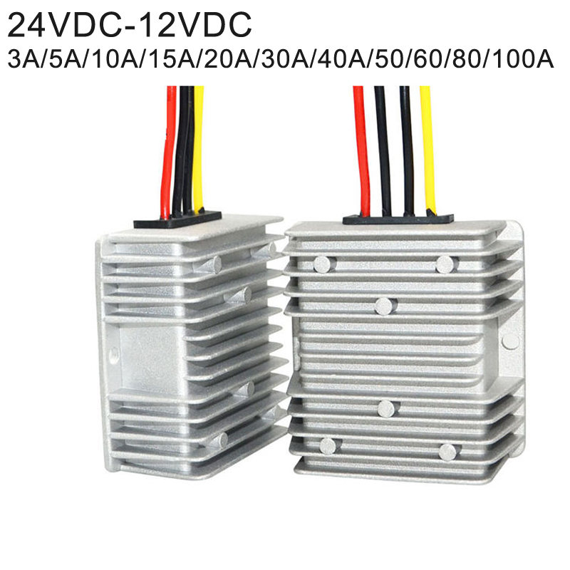
Start with the bus, not the load. A nominal 24V system does not sit at 24V — it rises during charging and sags under cranking load, and a converter specified against the nominal figure alone will drop out at the wrong moment. Write down the minimum and maximum your bus can reach, then choose a module whose published range covers both ends with margin.
Some loads accept a fixed rail; others want an adjustable one so a single part number covers several product variants. Decide early, because that choice eliminates whole families from the shortlist. Higher-power enclosed supplies often publish a continuous adjustment window, whereas compact step-down modules are specified at fixed outputs. The isolated SD-350 family in this portfolio is published as a multi-voltage instrumentation converter, which is the pattern to look for when related hardware needs several output rails.
Continuous current at a reference temperature is the starting point, not the answer. Take the published figure, add margin for start-up inrush, then apply the derating curve for the temperature the module will actually see. Treat peak ratings separately: a redundancy module rated 20A continuous may carry 30A for only five seconds.
A module quoting greater than 90% converts the remainder into heat, and that heat has to leave the enclosure. Where the module is potted and sealed, the very enclosure rating that protects it also traps its heat, so the derating curve matters more, not less. Chassis-mount formats remain popular because the chassis becomes part of the thermal path.
Confirm overload and over-temperature protection and verify the actual thresholds. The isolated SD-350 instrumentation family gives a usable benchmark: overload protection at 105% to 135% of rated output power, and an over-temperature function that shuts the output down and recovers automatically once the temperature falls. Its withstand voltage is published as 1.5 KVAC input-to-output and input-to-frame with 0.5 KVAC output-to-frame, over an isolation resistance of 100 MΩ at 500 VDC. Trip points must sit outside your load's normal envelope but inside its survival envelope.
For vehicle, solar, and outdoor telecom work the enclosure rating often decides the purchase. An IP68 waterproof and dustproof rating shields the unit against moisture, dust ingress, and vibration at once, which is the combination that matters on a moving vehicle or in an outdoor cabinet. Do not confuse the module rating with the rating of the assembly it sits in: a sealed housing with an unsealed cable entry delivers nothing.
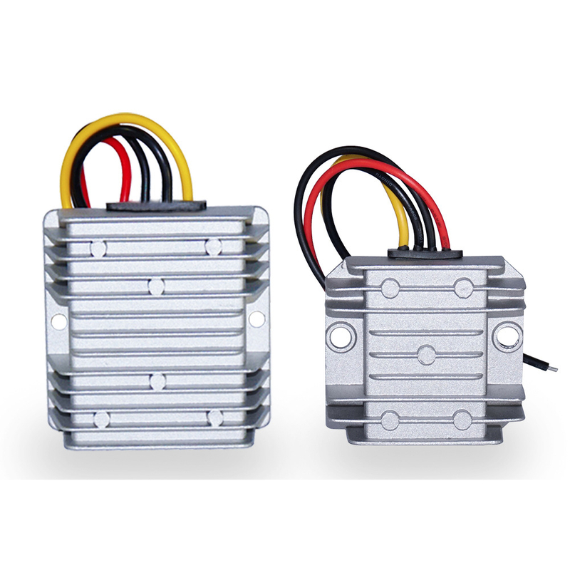
Assume a 24V nominal bus reaching 28V during charging and sagging to 20V under load, feeding a 12V rail that draws 8A continuously with a 12A inrush for 200 ms.
Step 1 — Confirm the input window. The bus spans 20V to 28V. A module specified only at 24V does not qualify; the published full DC-DC converter range includes families whose input windows cover it.
Step 2 — Convert to power, with margin. At 12V and 8A the steady load is 96W. Add 20% engineering margin for ageing and measurement tolerance, giving roughly 115W.
Step 3 — Check current separately. The steady draw is 8A and the inrush 12A. A 24V to 12V step-down converter covering 1.5A to 100A sits inside both, but confirm the inrush duration against the datasheet.
Step 4 — Apply thermal derating. Establish the cabinet ambient, then read the derating curve there. If the curve reduces the rating by 30% at your ambient, that reduced figure is your starting point.
Step 5 — Resolve the isolation question last. If the load needs its own reference, specify an isolated module such as the SD-350 family with its 1.5 KVAC input-to-output withstand voltage. If not, proceed with the non-isolated part.
Illustrative method only; not a SMUN product specification.
Undersized input wiring. A converter stepping 48V down to 13.8V at high current draws a deceptively large input current at the low end of its input range. Size conductors for worst-case input current, not the nominal figure.
Ignoring the return path. In a non-isolated design the return is shared, so any resistance in that path appears in both circuits. Bond the return properly rather than relying on a chassis joint.
Mounting a sealed module against a hot surface. Sealing insulates the electronics from the chassis as well as from the environment. Where a unit must be both sealed and chassis-mounted, verify derating with the real mounting arrangement.
Assuming redundancy comes for free. Redundancy is a separate component. A dedicated 20A DIN-rail redundancy module operating from 12V, 24V, or 48V DC supports 1+1 and N+1 configurations, and it must be budgeted for explicitly rather than assumed from the converter.
A non-isolated DC-DC converter module is the correct and economical answer whenever your load shares a reference with your source. The engineering case is simple: shared ground, no transformer barrier, smaller footprint, lower cost, and conversion efficiency typically above 90%.
The commercial case is equally simple, provided you specify properly. Take the input range from your bus, size current for the worst case, read the derating curve at your real cabinet ambient, and confirm protection thresholds against your load envelope. Where the application demands genuine separation, accept that an isolated module is the right part.
Before issuing an inquiry, confirm bus minimum and maximum, convert the load to power with margin, check inrush against the published peak rating, read the derating curve at your ambient, and settle whether your load can share a ground.
A: A DC-to-DC converter whose input and output share a common ground, with no transformer providing galvanic isolation. The 12V/24V to 5V non-isolated waterproof buck converter states its isolation type as "Non-Isolated (Common Ground)" and delivers 5V DC at up to 10A continuous with efficiency greater than 90%.
A: When the load needs a reference separate from the source: measurement front ends, isolated sensor interfaces, systems required to break a ground loop, and any application whose source and load grounds sit at different potentials. If none apply, a non-isolated module normally wins on footprint and cost.
A: Start from continuous output current, add margin for start-up inrush, then apply the derating curve for your enclosure's ambient temperature. Peak figures are time-limited — 20A continuous may mean 30A for only five seconds — so treat continuous and peak as separate constraints.
A: No. Even a module above 90% converts the remainder into heat, and a sealed housing that protects the electronics also traps that heat. The derating curve at your real cabinet ambient governs what the module can deliver.
A: IP68 waterproof and dustproof enclosures are common for vehicle, solar, and outdoor telecom installations because they shield the unit against moisture, dust ingress, and vibration at once. Confirm the connection method too: a sealed housing with an unsealed cable entry does not deliver the rating claimed.