
- All
- Product Name
- Product Keyword
- Product Model
- Product Summary
- Product Description
- Multi Field Search

Views: 0 Author: Site Editor Publish Time: 2026-08-10 Origin: Site


Intermittent automation failures frustrate engineers endlessly. Unexplained PLC resets disrupt critical manufacturing workflows. Spurious logic triggers and drifting sensor readings waste valuable production time. We often overlook the fundamental root cause behind these phantom faults in 24VDC control cabinets. The hidden culprit is usually power supply output ripple. Dirty DC power subtly destabilizes perfectly configured automation networks. It forces sensitive components to operate outside their designated electrical parameters.
This article objectively evaluates how electrical noise degrades overall control system stability. You will learn the exact mechanisms behind these logic disruptions. We will also explore how to properly specify the right power architecture. Making informed decisions here prevents costly, unexpected machine downtime in your facilities.
Excessive power supply output ripple can violate PLC logic thresholds and degrade the accuracy of high-resolution analog sensors.
Standard industry practice demands ripple and noise remain below 1% of the nominal output voltage (e.g., <120mVp-p for a 24V system) under full load.
Evaluating an Industrial Power Supply requires looking beyond datasheet "typical" values to understand how ripple performs under dynamic loads and thermal stress.
Upgrading to a high-quality DIN Rail Power Supply with premium low-ESR capacitors mitigates long-term ripple degradation caused by cabinet aging.
Microscopic electrical anomalies easily translate into macroscopic business losses. A brief voltage fluctuation might last only a few milliseconds. However, it can halt an entire packaging line. Unplanned machine downtime costs facilities thousands of dollars per minute. Compromised batch quality leads to expensive material waste. Diagnostic labor hours pile up quickly as maintenance teams chase invisible electrical ghosts.
Technicians often incorrectly blame the PLC firmware when errors occur. They might replace perfectly good analog sensors. They rewire network cables hoping to fix communication drops. These interventions fail because they treat the symptoms. The actual failure point is dirty DC power. No firmware update can fix an unstable power delivery system. Rewiring does nothing if the source voltage itself fluctuates wildly.
You must establish strict success criteria for a stable power architecture. True stability means the voltage stays strictly within tight tolerance bands. Sensitive microprocessors require flat, continuous DC power. Analog-to-digital converters (ADCs) demand a clean noise floor to function correctly. A successful design maintains these parameters regardless of heavy load steps. When a large motor starts, the DC bus must not sag or ring. Securing this foundation eliminates the majority of unexplained cabinet faults.
Digital inputs on 24VDC PLCs rely on specific voltage thresholds to read logic states. We call these thresholds $V_{IL}$ (Voltage Input Low) and $V_{IH}$ (Voltage Input High). A typical PLC might recognize any voltage below 5V as a logical "0". It might recognize any voltage above 15V as a logical "1". The area between 5V and 15V is an undefined region. High-amplitude voltage ripple can push a valid signal into this undefined zone. If a steady 24V signal experiences a severe negative ripple spike, the PLC might momentarily read a "0". This causes false triggering. A safety relay might trip. A sequencer might skip a crucial step.
Modern PLCs do feature internal filtering networks. These circuits help smooth out minor electrical anomalies. However, you cannot rely entirely on them. Sustained high-frequency transients easily bypass basic input filters. Severe low-frequency ripple overloads internal decoupling capacitors. Once the noise passes the front-end isolation, it corrupts the primary logic processor. Proper power conditioning at the source remains your best defense.
Analog circuits suffer even more from excessive ripple. Standard 0-10V or 4-20mA loops require absolute voltage stability. A pressure sensor translating physical force into a 4-20mA signal assumes the base voltage remains perfectly flat. Ripple injects direct interference into this translation process. The sensor transmits a fluctuating signal. The controller misinterprets the physical reality.
Noise floors directly dictate ADC resolution. Modern automation utilizes 16-bit or even 24-bit ADCs for high-precision tasks. A 16-bit ADC running on a 10V reference has a Least Significant Bit (LSB) size of roughly 0.15mV. If your power source injects 50mV of ripple, it effectively buries the lowest bits in noise. This introduces unacceptable quantization errors. You pay for 16-bit accuracy but only receive 8-bit performance.
ADC Resolution | Reference Voltage | LSB Value | Impact of 50mV Ripple | Effective Resolution Lost |
|---|---|---|---|---|
10-bit | 10V | 9.76 mV | Swallows ~5 LSBs | Mild loss |
12-bit | 10V | 2.44 mV | Swallows ~20 LSBs | Noticeable degradation |
16-bit | 10V | 0.15 mV | Swallows ~330 LSBs | Severe quantization error |
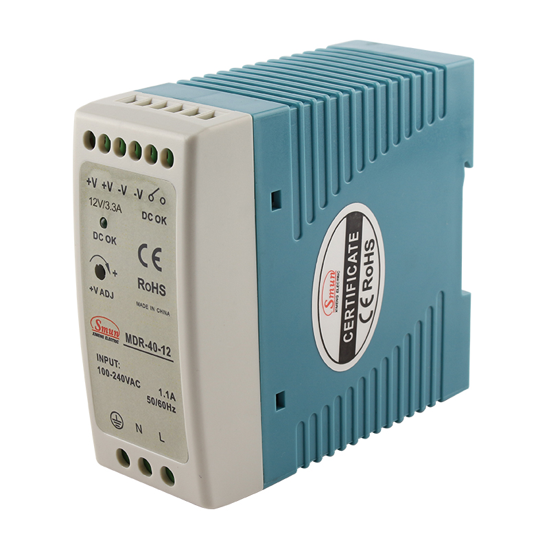
Industry standards provide clear baselines for acceptable noise levels. Standard practice demands ripple and noise remain below 1% of the nominal output voltage. For a robust 24V industrial system, this means keeping noise below 240mVp-p. However, high-quality units aim much lower. A premium Industrial Power Supply typically restricts ripple to less than 120mVp-p. Instrumentation networks and laboratory-grade sensors require even tighter tolerances. They often demand sub-50mVp-p performance to maintain data integrity.
Engineers must read datasheets critically. You must differentiate between low-frequency ripple and high-frequency noise. Low-frequency ripple usually originates from the input AC mains. It appears at twice the line frequency (e.g., 100Hz or 120Hz). High-frequency noise consists of sharp switching artifacts. These spikes occur at the regulator's switching frequency, often between 50kHz and 500kHz.
Always scrutinize the test conditions listed on the datasheet. A "typical" specification means very little in harsh environments. Ask yourself these critical questions:
Was the ripple measured at a strict 20MHz bandwidth?
Did the manufacturer test the unit under full load or partial load?
Was the test conducted at a mild 25°C or at realistic cabinet operating temperatures?
You must also evaluate the fundamental tradeoff between linear and switching regulators. Linear regulators provide ultra-low ripple. They produce almost zero switching noise. Unfortunately, they generate excessive heat and lack efficiency. Switching regulators operate with high efficiency. They stay cool under heavy loads. However, they inherently generate switching noise. They require superior internal filtering components to clean the output voltage.
Regulator Type | Typical Efficiency | Ripple & Noise Output | Thermal Output (Heat) | Best Application |
|---|---|---|---|---|
Linear | 30% - 50% | Extremely Low (<10mV) | Very High | Lab instruments, audio gear |
Switching (SMPS) | 85% - 95% | Moderate (50mV - 200mV) | Low | Factory automation, PLCs |
Cabinet space is a premium resource in modern automation. A typical DIN Rail Power Supply operates in constrained, unventilated spaces. Multiple devices sit packed closely together. This creates high thermal density. Heat acts as the primary enemy of power electronics. High thermal density degrades internal electrolytic capacitors much faster. As the liquid electrolyte vaporizes over time, the Equivalent Series Resistance (ESR) increases. Higher ESR directly leads to increased output ripple. Your system might run perfectly on day one but fail inexplicably two years later.
You must evaluate power units across several critical dimensions mapping features to outcomes. Follow these guidelines:
Capacitor Quality: Look for models explicitly specifying high-temperature (105°C rated), low-ESR capacitors. These components resist thermal degradation and maintain flat voltage profiles over years of continuous use.
Dynamic Load Response: The supply must maintain its ripple specifications even during sudden current surges. Inductive loads like contactors and solenoids frequently fire on the same DC bus. The power unit must recover instantly without exhibiting severe voltage dips or ringing.
Integrated EMI/RFI Filtering: Look for extensive onboard filtering. This ensures high-frequency switching noise does not bleed backward into the AC grid. It also stops noise from surging forward into the delicate PLC logic board.
Do not simply buy the unit with the highest wattage. Oversizing a switching power supply sometimes results in poorer load regulation. Many units operate less efficiently at 10% load than at 80% load. Focus carefully on the load regulation percentage. Verify the ripple specifications under maximum rated operating temperatures. Finally, check the MTBF (Mean Time Between Failures) documentation to guarantee long-term reliability.
Measuring noise incorrectly leads engineers down the wrong diagnostic path. Standard oscilloscope probes often cause massive measurement pitfalls. They typically use a long ground lead with an alligator clip. This long wire acts as an antenna. It actively picks up ambient electromagnetic interference (EMI) from variable frequency drives and relays inside the cabinet. The scope screen displays artificially inflated ripple readings.
To avoid this trap, use the "tip-and-barrel" or ground-spring method. Remove the standard ground clip entirely. Attach a short, bare ground spring directly to the probe barrel. Press this assembly directly against the output terminals. This eliminates the antenna effect. You will capture the true, uninflated ripple voltage.
Even the best power supply requires proper deployment best practices. Consider these crucial steps during cabinet assembly:
Separate your routing paths. Never run sensitive analog signal wires parallel to high-current DC power lines or AC mains.
Use localized decoupling capacitors near highly sensitive instrumentation.
Deploy dedicated DC-DC converters to isolate critical measurement nodes. This prevents noise from a shared 24V bus from cross-contaminating your precision instruments.
Be aware of severe adoption risks. Upgrading a power unit without addressing fundamental wiring flaws will not solve your noise problems. Ground loops represent a massive threat to automation stability. If your cabinet suffers from multiple conflicting ground potentials, noise will circulate regardless of the supply quality. You must secure a single-point star ground architecture. Only then can a premium filtered power supply truly protect your PLCs and sensors.
Power supply output ripple is not a mysterious electrical phenomenon. It is a strictly measurable, highly solvable variable. It heavily dictates the overarching reliability of your automation equipment. Controlling this noise prevents random logic resets. It preserves the exact accuracy of your analog control loops. Ignoring it guarantees frustrating, intermittent production halts.
Take proactive steps today to secure your machine architecture. First, audit your current power supply datasheets. Compare their stated ripple limits against the strict voltage tolerances of your installed PLCs and sensors. Second, mandate proper measurement techniques using the tip-and-barrel method to verify actual cabinet conditions. Finally, consider upgrading to heavily filtered, industrial-grade DIN rail units for all mission-critical nodes. Investing in clean power upfront prevents immense diagnostic costs later.
A: Yes. As internal capacitors age and dry out (especially in hot environments), their Equivalent Series Resistance (ESR) increases, causing ripple voltage to rise as the unit nears its end of life.
A: Not recommended. Commercial supplies lack the ruggedized EMI filtering and strict ripple control required for industrial environments, risking PLC logic errors during factory electrical surges.
A: Ripple is a periodic variation corresponding to the switching frequency or AC line frequency. Transient noise consists of random, high-frequency spikes typically caused by inductive load switching. Both require different filtering approaches.