
- All
- Product Name
- Product Keyword
- Product Model
- Product Summary
- Product Description
- Multi Field Search
Views: 0 Author: Site Editor Publish Time: 2026-08-24 Origin: Site


Industrial control system downtime costs thousands of dollars per minute. Power supply failure ranks as a leading, yet easily preventable, cause of control cabinet crashes. Modern power components boast high Mean Time Between Failures (MTBF). Still, isolated component breakdowns or unexpected external grid anomalies occur regularly. Evaluating whether you need to implement DIN rail power supply redundancy requires careful planning. You must balance cabinet space and upfront component costs against your acceptable risk threshold. You must also weigh the strict technical realities of your load requirements to prevent sudden system failure. In this article, you will learn the exact difference between parallel wiring and true N+1 redundancy. We will explore specific industrial scenarios where redundancy is mandatory. You will also discover how to select the appropriate hardware to safeguard your most critical automation loads effectively.
N+1 Redundancy vs. Parallel: Simply wiring two power supplies together increases capacity but does not provide true redundancy without a decoupling mechanism.
Risk Thresholds: N+1 redundancy is mandatory for hazardous locations (e.g., Zone 2 / Div 2), continuous process manufacturing, and critical safety instrumented systems (SIS).
Component Necessity: A dedicated DIN Rail Redundancy Module is required to isolate a failed power supply and prevent it from shorting the functional units.
Cost Efficiency: N+1 provides a more cost-effective and space-saving safety net for high-load systems compared to 1+1 or 2N architectures.
Engineers often misunderstand the industrial standard for N+1 redundancy. We must define the terms clearly. "N" represents the exact number of power supplies required to support your full system load. The "+1" represents a single independent backup unit. If your system requires 20 amps to function, you might use two 10A power supplies to handle the load. That is your "N". Adding a third 10A power supply creates the "+1". This ensures your system stays online if one unit fails.
A dangerous misconception plagues control panel design. Many engineers believe wiring standard power supplies in parallel creates redundancy. This is fundamentally incorrect. Simply connecting output terminals increases total capacity, but it introduces a severe risk. If one power supply experiences an internal short circuit, it acts as a load. It will instantly pull down the voltage of the entire DC bus. Your critical system will crash immediately.
True redundancy requires strict isolation between power units. You must use decoupling devices, such as diodes or MOSFETs, to separate the power supplies. This decoupling guarantees a seamless switchover without any voltage dips during a hardware fault. If one unit fails, the isolation prevents it from drawing power away from the surviving units. Your system load remains completely unaffected.
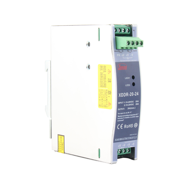
Continuous process manufacturing demands absolute uptime. This applies heavily to pharmaceutical blending, chemical processing, and semiconductor fabrication. A sudden power loss forces controllers and PLCs to reboot. This brief interruption ruins active production batches. Scrapped materials cost thousands of dollars. Recalibrating sensors and cleaning pipelines waste hours of valuable production time. Redundancy prevents these catastrophic operational gaps.
Some systems operate in potentially explosive atmospheres. ATEX Zone 2 and Class I Div 2 environments require strict environmental safety controls. Power stability directly ties to facility safety. If a power supply fails, critical ventilation fans, gas monitors, or emergency shutdown systems might go offline. Regulatory compliance mandates redundant architectures in these zones. A failure here risks human lives, not just production output.
Maintenance crews cannot instantly reach every facility. Offshore wind platforms, remote water treatment plants, and unstaffed telecom nodes present unique challenges. Dispatching a technician to replace a failed power supply often takes days. These facilities require a fault-tolerant buffer. A redundant backup keeps the site operational while maintenance teams schedule a service visit. It eliminates the need for expensive emergency helicopter or boat dispatches.
Modern factories blend IT and OT environments. Industrial control cabinets now house enterprise-grade edge computing devices and industrial Ethernet switches. These data-heavy components require data center levels of uptime. A brief power dip causes network switches to reboot, severing communication across the factory floor. Implementing N+1 logic protects this sensitive IT infrastructure from harsh industrial power anomalies.
Choosing the right architecture requires evaluating your acceptable risk levels and budget constraints. We must analyze how different redundancy setups handle power distribution.
This setup uses one primary DIN Rail Power Supply to handle 100% of the load. A second identical unit sits in backup, also capable of handling 100% of the load. This is best for smaller control panels and low-power control loops. However, duplicating the entire load capacity wastes space. It becomes highly inefficient as your system power requirements scale up.
This configuration uses multiple smaller units to share the load. For example, three 10A units support a 20A load. This architecture excels in high-power applications. Duplicating a massive 40A load with a 1+1 setup is cost-prohibitive. It also generates excessive heat that exceeds DIN rail thermal limits. N+1 offers a scalable, space-saving safety net.
The 2N approach duplicates the entire power infrastructure. Two independent power systems feed from entirely different AC mains. If a factory electrical panel blows, the second system keeps the cabinet running. This is reserved for zero-tolerance, mission-critical infrastructure where even a primary AC grid failure is unacceptable.
You must weigh initial hardware CapEx and cabinet width against the statistical cost of a single unmitigated failure. Use the table below to guide your design choices.
Configuration Strategy | Power Distribution Setup | Ideal Implementation Case | Cabinet Space Impact |
|---|---|---|---|
1+1 Redundancy | 1 Primary (100%), 1 Backup (100%) | Low-power panels, tight budget setups | High relative to load size |
N+1 Redundancy | Shared load across multiple units + 1 backup | High-current systems, process manufacturing | Highly optimized |
2N Redundancy | Fully duplicated A and B power feeds | Life safety systems, hazardous zones | Maximum space required |
You cannot achieve true isolation without specialized hardware. A DIN Rail Redundancy Module serves as the critical gatekeeper. You must choose between two distinct decoupling technologies.
Diode-based modules represent the traditional approach. They are highly reliable and simple in design. However, diodes inherently cause a forward voltage drop of roughly 0.7V. In a 20A system, this translates to 14 watts of pure heat. This thermal load complicates cabinet cooling.
MOSFET-based modules utilize modern semiconductor switching. They drastically reduce the voltage drop to approximately 50 millivolts. This lowers heat generation significantly. MOSFET modules are highly recommended for continuous high-current loads enclosed in tight control cabinets.
Redundancy modules often facilitate active load sharing. This balances the current symmetrically across all "N" units. Without load sharing, one primary supply runs at 100% capacity while the backup sits idle. Heat accelerates electronic wear. A component running constantly at high temperatures will fail much faster. By balancing the load, you reduce the thermal stress on individual units. This prevents premature thermal aging and extends the lifespan of your hardware.
Your wiring practices directly impact system reliability. You must use symmetrical cable lengths between the power supplies and the redundancy module. Unequal lengths create varied resistance levels. This forces one power supply to carry a disproportionate amount of the load. Additionally, wire sizing must accommodate the maximum potential current during a fault sequence. Ensure your AWG rating exceeds the expected peak load.
Redundancy is entirely useless if a failure goes unnoticed. If the primary unit fails silently, you lose your backup net. The next failure crashes your system. Demand modules with relay contacts, commonly known as DC OK alarms. Modern systems may even utilize IO-Link digital interfaces. These connections immediately notify your PLC or SCADA system the moment the "+1" unit engages. Immediate notification allows maintenance to replace the failed unit promptly.
Heat rises. You will typically mount power components near the top of the control cabinet. This is the hottest zone in the enclosure. Assess how the redundancy module performs under full load at elevated temperatures. Review the manufacturer's thermal derating curve. A module rated for 20A at 40°C might only support 15A when ambient cabinet temperatures reach 60°C.
Deployment environments dictate your compliance requirements. Standard commercial modules will not survive harsh industrial settings. Verify that your chosen hardware possesses necessary UL and CE marks. If deploying on ships or offshore rigs, demand marine certifications like DNV GL. Hazardous locations strictly require ATEX or Class I Div 2 approvals.
Engineers must choose between proprietary ecosystems and agnostic hardware. Using matching power supplies from a single vendor simplifies mounting and aesthetic panel layout. However, universal redundancy modules offer flexibility. They support mixed-vendor setups. This proves invaluable during supply chain shortages. You can easily integrate a different brand of power supply without replacing the entire redundant architecture.
Implementing N+1 DIN rail power supply redundancy goes far beyond basic system upgrades. It functions as a mandatory insurance policy for your most critical automation loads. Simple parallel wiring creates false confidence and introduces severe short-circuit risks. By investing in proper decoupling hardware, you isolate failures and ensure seamless continuous operation.
Your next steps require practical assessment. Audit your control cabinet to determine your total current draw. Calculate the financial impact a one-hour unexpected shutdown would cost your facility. Finally, select a dedicated redundancy module that utilizes either Diode or MOSFET technology to perfectly align with your specific thermal and spatial constraints.
A: Yes, you can use different brands if they are decoupled by a universal redundancy module. However, using identical models is strongly recommended. Matching units ensure consistent voltage output, predictable transient response, and highly accurate load sharing capabilities across the entire redundant architecture.
A: Passive redundancy, or hot standby, keeps the backup unit entirely idle until the primary fails. Active redundancy continuously shares the operational load across all connected units. This active approach significantly reduces thermal stress on individual components and improves the overall mean time between failures.
A: It only protects against AC input failures if the redundant power supplies are fed from separate AC mains or phases. If all power units share the exact same failing AC line, the DC output will still drop. You must pair the system with a UPS to bridge total AC loss.