Mode decides the filter element. Differential noise travels line to neutral and needs X-capacitors; common-mode noise returns through earth and needs chokes plus Y-capacitors.
Common mode is harder to contain. The loop includes the chassis and building earth, so the noise both conducts and radiates into nearby cables.
Measure before specifying. A LISN and spectrum analyzer give the amplitude and band of the emission, which sets the attenuation target.
Compare against the limit line. The gap between the measured peak and the regulatory limit, not the absolute level, sizes the filter.
One stage covers small margins. A single LC network is normally enough when the shortfall is modest across the band.
Two stages cover large margins. Cascaded networks steepen the curve in the low band where switching noise is hardest to suppress.
Introduction
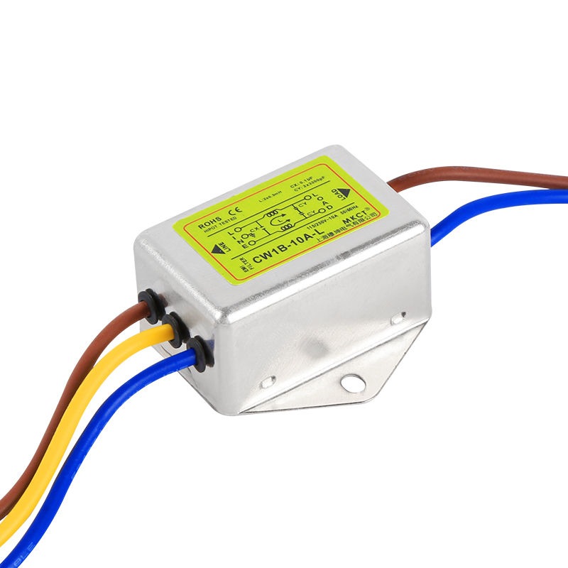
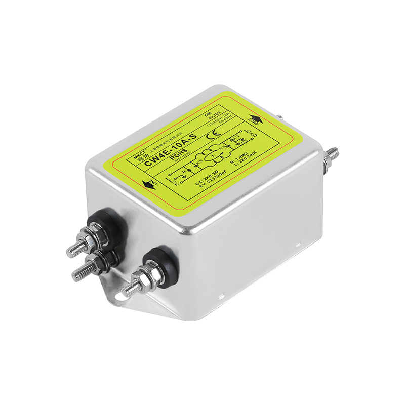
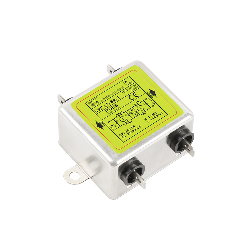
An emi noise filter is a vital passive electronic component utilized to suppress electromagnetic interference on power and signal lines. It functions by heavily attenuating both common-mode and differential-mode high-frequency noise, ensuring electrical compliance and the reliable operation of sensitive industrial equipment connected to the electrical grid.
The proliferation of high-speed switching electronics in industrial environments has elevated electromagnetic compatibility (EMC) from an afterthought to a primary engineering constraint. Without proper noise mitigation strategies, equipment can experience severe operational degradation, data corruption, and catastrophic hardware failures. Implementing the correct filtering topology is not a generic process; it requires a granular understanding of the specific noise characteristics present in the system. By diagnosing the exact nature of the interference, engineers can deploy the most effective filter stages to sanitize the power feed.
Common Mode vs Differential Mode Noise: What’s the Difference?
The Mechanics of Differential-Mode Interference
In AC power distribution systems, differential-mode (DM) noise, also referred to as symmetrical noise, is the interference signal that travels on the line (Live) conductor and returns via the neutral conductor. The noise current flows in opposite directions in these two lines, directly superimposing itself onto the fundamental AC waveform. This type of noise is typically generated by fundamental switching operations within the equipment itself, such as the rapid turn-on and turn-off transients of rectifiers, power factor correction (PFC) circuits, and basic motor switching.
Because the noise loop is contained strictly between the power and neutral lines, it primarily affects the power delivery directly at the component level, causing voltage spikes and dips that can stress internal power supply components and corrupt low-voltage DC rails if not adequately suppressed.
The Pathways of Common-Mode Interference
Conversely, common-mode (CM) noise, or asymmetrical noise, behaves entirely differently. This interference signal travels simultaneously and in the same direction on both the line and neutral conductors, and it returns to the source through the earth ground connection. CM noise is predominantly caused by parasitic capacitive coupling—such as the capacitance between a high-frequency switching transistor and a grounded heatsink within a variable frequency drive (VFD).
Because the noise loop includes the physical chassis and the facility grounding system, CM noise is notoriously difficult to control. It has a high propensity to radiate into the surrounding environment as airborne electromagnetic interference or couple into adjacent sensitive communication cables. Therefore, an effective ac emi filter must possess specific circuit elements, namely common-mode chokes and Y-capacitors, specifically engineered to block this ground-path interference and shunt it harmlessly away from the protected equipment.
Table 1: Common Mode and Differential Mode Side by Side
Property
Differential mode
Common mode
Current path
Line to neutral, opposite directions
Line and neutral to earth, same direction
Also called
Symmetrical noise
Asymmetrical noise
Typical source
Rectifiers, PFC stages, motor switching
Parasitic capacitance to a grounded heatsink
Loop includes chassis
No
Yes
Filter elements
X-capacitors and differential chokes
Y-capacitors and common-mode chokes
Tendency to radiate
Lower
Higher
The stage count usually follows the current rating and the mounting style rather than the brochure headline. A 3A to 30A single-phase EMI power filter covers most panel feeds in one stage, while a 250VAC line-type filter fits equipment where the inlet sits on a short internal harness.
How to Measure EMI for Accurate Filter Selection
Deploying LISNs and Spectrum Analyzers
The accurate selection of a filtering solution relies entirely on precise empirical data, not estimations. In a professional EMC testing laboratory, the foundational tool for this analysis is the Line Impedance Stabilization Network (LISN). The LISN serves a dual purpose: it provides a standardized, known impedance across the frequency spectrum for the equipment under test (EUT) to operate against, and it isolates the EUT from the ambient noise already present on the utility power grid.
The noise output from the LISN is then fed into a high-bandwidth spectrum analyzer or an EMI receiver. This instrumentation allows test engineers to visualize the exact amplitude and frequency profile of the conducted emissions generated by the device, sweeping typically from 150 kHz to 30 MHz. This detailed spectral mapping is the critical first step in defining the required attenuation parameters for the filter.
Analyzing the Conducted Emission Profile
Once the raw spectral data is captured, the analysis phase determines the necessary filter specifications. Engineers compare the measured emission levels against the limit lines defined by regulatory standards (such as CISPR, EN, or FCC). The delta between the peak noise emissions and the allowable limit dictates the required insertion loss of the filter at specific frequencies. For example, if a machine exceeds limits significantly in the 1 MHz to 5 MHz band, the selected single phase filter must exhibit a sharp attenuation curve in that precise range.
Furthermore, advanced diagnostic techniques can isolate the noise into its common-mode and differential-mode components. This separation is crucial; if the spectrum analyzer reveals that the dominant noise failure is differential-mode at lower frequencies, the engineer knows to specify a filter topology heavily weighted with X-capacitors and differential-mode inductors, rather than relying solely on common-mode chokes.
Table 2: Building a Conducted Emission Measurement
Step
Instrument or setup
What it establishes
Decision it drives
Stabilise impedance
LISN
Known impedance at the test port
Repeatable readings
Isolate ambient noise
LISN filter section
Noise floor of the room
Whether a reading is real
Sweep the band
Spectrum analyzer or EMI receiver
Amplitude against frequency
Attenuation target
Compare with limits
Limit lines for the product family
Margin at each frequency
Stage count
Separate the modes
Mode separator or probe
Which mode dominates
X or Y component choice
Single-Stage vs Two-Stage EMI Filters: Which is Better?
Applications for Single-Stage Filtering Topologies
Single-stage filters consist of one complete LC (inductor-capacitor) circuit network. These are the workhorses of standard industrial applications, offering a balance of physical compactness, cost-effectiveness, and moderate noise suppression capabilities. A typical single-stage design is highly effective at attenuating broadband interference in environments with predictable, lower-amplitude noise profiles. They are frequently deployed in standard commercial power supplies, basic motor controls, and general-purpose automation panels where the noise floor is relatively stable.
If the EMC pre-compliance testing shows that the equipment fails the limits by only a modest margin (e.g., 5 to 15 dB) across the required frequency spectrum, a high-quality single-stage filter is usually the most efficient and economical engineering choice to achieve regulatory compliance without unnecessarily increasing the bill of materials cost.
When to Upgrade to a Two-Stage Filtering Network
However, when the equipment operates in extremely harsh electrical environments or generates aggressive, high-amplitude switching transients, a single-stage design will likely fall short. This is where a two stage emi filter becomes mandatory. These filters essentially cascade two independent LC networks within a single enclosure. This dual-stage architecture dramatically steepens the insertion loss curve, providing vastly superior attenuation, particularly in the lower frequency bands (10 kHz to 1 MHz) where switching noise is most difficult to suppress.
Two-stage filters are critical for high-power variable frequency drives (VFDs), large-scale welding equipment, high-frequency induction heaters, and any application where the initial noise measurements exceed regulatory limits by 20 dB or more. While physically larger and more costly, the two-stage topology supports robust compliance and prevents severe electromagnetic pollution in demanding industrial installations.
Table 3: Single-Stage Against Two-Stage Filtering
Criterion
Single stage
Two stage
Circuit
One LC network
Two cascaded LC networks
Attenuation slope
Moderate
Steeper
Low-band performance
Limited
Stronger
Size and mass
Smaller
Larger
Cost
Lower
Higher
Fits when
Margin is small and the noise floor is stable
Margin is large or the load switches hard
Conclusion
Effectively mitigating electromagnetic interference requires a precise understanding of the noise signature generated by your equipment. Differentiating between common-mode and differential-mode noise is the fundamental first step in defining an appropriate suppression strategy.
By accurately measuring the conducted emission profile using standardized laboratory equipment, engineers can transition from guesswork to precision engineering, selecting the exact filter topology required. Whether an application demands a streamlined single-stage solution for moderate noise or a heavy-duty two-stage network for aggressive transients, deploying the correctly specified emi noise filter ensures robust operational stability and supports compliance with global EMC directives. Filters built for single-phase panel feeds are listed in the single-phase filter range when you need to compare current ratings side by side.
Q: How do I tell common-mode from differential-mode noise?
A: Measure with a LISN and a mode separator, or compare readings taken line-to-neutral and line-to-earth. Noise that appears mainly between line and neutral is differential; noise that appears between each line and earth, in the same phase, is common mode.
Q: Why does common-mode noise radiate more?
A: Its return path runs through the chassis and the building earth, which form a large loop that behaves like an antenna. Differential noise stays in a tight loop between two conductors, so the field it produces falls away much faster with distance.
Q: Is a two-stage filter always better?
A: No. It costs more, occupies more space and adds insertion loss in a band you may not need. Choose it when the measured shortfall is large or when the load switches hard enough that a single network cannot hold the limit across the band. Start with one stage and let the measurement decide.
Q: Which capacitor types handle which mode?
A: X-capacitors sit across line and neutral and address differential noise; Y-capacitors connect each line to earth and address common-mode noise. Increasing Y-capacitance raises earth leakage, so the safety limit caps how far that route can go.
Q: Can one filter serve several machines in a cabinet?
A: Only if the feed and the return paths are arranged so that each machine sees the filter. Shared filters often leave a direct path between noisy and quiet loads, which is why a bolt-connection single-phase filter is mounted per enclosure rather than per panel row.