
- All
- Product Name
- Product Keyword
- Product Model
- Product Summary
- Product Description
- Multi Field Search

Views: 0 Author: Site Editor Publish Time: 2026-10-02 Origin: Site


In industrial automation and control panels, unreliable power delivery frequently halts production lines. It remains a primary failure point for PLCs, sensors, and communication modules. Engineers often over-specify or under-specify power components during initial panel design. They typically misunderstand how input voltage ranges and galvanic isolation actually perform under real-world stress. This misunderstanding drives up initial hardware expenses unnecessarily. Worse, it creates severe system vulnerabilities, exposing sensitive logic boards to destructive ground loops and transient voltage spikes.
We designed this guide to help you build a more robust power architecture. You will find a concrete, decision-focused framework for evaluating input tolerances below. We also explore strict isolation requirements specifically tailored for industrial panel environments. By mastering these core concepts, you can protect sensitive equipment, streamline your design process, and prevent unexpected field failures before they happen.
Power sources in industrial settings rarely provide a perfect, flat voltage curve. Understanding how a converter handles these fluctuations requires a close look at input voltage ratios. Manufacturers usually define these ranges as 2:1, 4:1, or 8:1 ratios. These numbers represent the maximum input voltage divided by the minimum input voltage.
For example, a nominal 24V system might use a 2:1 converter. This unit accepts anything from 18V to 36V. A 4:1 converter designed for the same 24V nominal bus might accept 9V to 36V. An ultra-wide 8:1 converter could stretch from 9V all the way to 75V. Choosing the right ratio directly impacts how well your equipment survives daily environmental electrical stress.
A wide input range proves mandatory for any battery-backed system. Lead-acid or lithium battery banks fluctuate significantly based on their charge state. A 24V battery bank might sit at 27.6V during a bulk charge. However, it can drop below 19V during a deep discharge cycle. If you select a converter with a narrow input window, the system will shut down prematurely. You lose critical monitoring capabilities when the battery voltage sags below the converter's operational threshold.
Load switching causes similar headaches. When large motors, solenoids, or actuators start up on a shared DC bus, they draw massive inrush currents. This sudden demand pulls the local bus voltage down sharply for a few milliseconds. These localized voltage sags easily trip sensitive logic controllers. A 4:1 or 8:1 converter easily rides through these momentary dips, keeping downstream electronics stable.
Engineers face a distinct trade-off when selecting input ranges. Wider input ranges offer tremendous versatility. They allow procurement teams to consolidate SKUs. You can use one 4:1 converter model across both 12V and 24V control panels. This reduces inventory complexity.
However, this versatility brings compromises. Extremely wide input ranges often force designers to accept slightly lower peak electrical efficiency. The internal switching components must work harder to step down a 75V input compared to a stable 24V input. Furthermore, high-ratio converters generally command a higher purchase price due to more complex internal magnetic designs. You should specify wider ranges only where bus volatility demands it.
Galvanic isolation physically separates the input and output circuits within a power supply. It prevents direct current from flowing between the primary power source and the secondary load. Energy transfers across this barrier using magnetic fields inside a transformer or via light waves inside an optocoupler. This physical gap acts as an invisible shield for your electronics.
Before specifying a component, you must evaluate the operating environment carefully. Non-isolated converters share a common ground between input and output. They cost less, operate highly efficiently, and occupy a smaller physical footprint. We typically use them for localized point-of-load regulation where ground potentials remain perfectly stable.
Isolated converters cost more and require more space. However, harsh industrial environments absolutely require them. To simplify your selection process, review the chart below.
Chart: Isolated vs. Non-Isolated Converter Decision Matrix| Evaluation Criteria | Non-Isolated Converters | Isolated Converters |
|---|---|---|
| Common Grounding | Input and output share a ground. | Input and output grounds are completely separated. |
| Primary Application | Point-of-load (PoL) regulation on a single stable PCB. | Harsh factory floors, remote sensors, communication nodes. |
| Noise Immunity | Low. Susceptible to bus noise. | High. Blocks common-mode electrical noise. |
| Footprint & Cost | Highly compact and generally inexpensive. | Larger due to internal transformers; higher initial price. |
The primary reason engineers mandate isolation is ground loop elimination. In large factories, grounding points at different ends of a building rarely sit at the exact same electrical potential. If you connect an analog sensor or an RS-485 communication bus across two different ground potentials without isolation, stray currents flow through the data cables. These stray currents corrupt data packets and degrade analog signal accuracy.
Fault isolation serves as the second major driver. Imagine a catastrophic short circuit occurring on a high-voltage primary bus. An isolated converter contains that failure. It prevents a massive voltage spike from crossing the barrier and frying the delicate secondary-side microcontrollers.
Finally, regulatory compliance dictates isolation limits. Systems designed for medical, railway, or explosive environments must meet stringent safety standards. Standard IEC/UL 62368-1 often requires specific dielectric withstand voltages, such as 1.5kV, 3kV, or 4kV, to guarantee operator safety during fault conditions.
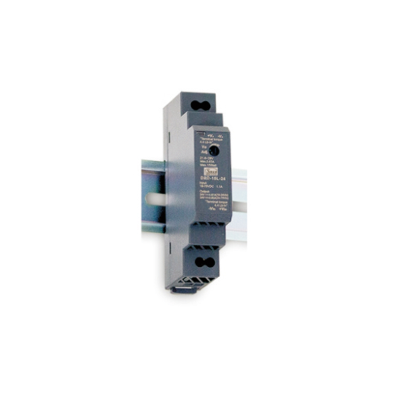
Industrial panel design requires looking beyond basic electrical specifications. When evaluating a DIN rail DC DC converter, the form factor dramatically influences system reliability. You must translate laboratory PCB-level specifications into control cabinet realities.
Mounting matters immensely. A converter soldered onto an open-air circuit board experiences very different thermal dynamics than one clamped tightly to a metal rail. Industrial control cabinets suffer from severe localized heat buildup. Motor drives, power supplies, and contactors all generate thermal energy. Because IP67 or highly sealed IP20 cabinets lack forced-air cooling, your chosen converter must survive through natural convection alone.
The unit must maintain its precise isolation integrity and strict input regulation while baking in ambient temperatures that easily exceed 60°C. If the internal potting or component spacing warps under heat, the isolation barrier fails.
When selecting your next DIN rail DC DC converter, apply these three rigorous evaluation criteria:
Best Practice: Always leave at least 5 millimeters of spacing on either side of a convection-cooled module. This gap allows vertical airflow to pull heat away from the chassis.
Let us apply this evaluation framework to a practical scenario. Imagine you need to specify a low-power solution for a distributed control node. This node functions as an IoT gateway inside a noisy automotive manufacturing plant. The gateway pulls data from legacy serial devices and pushes it to an industrial Ethernet backbone.
A module like the DDR-15 DC-DC converter fits this scenario perfectly due to its specific engineering traits. First, we examine input range validation. This 15-watt device features an ultra-wide 4:1 input capability. It comfortably accepts either 9-36V or 18-75V depending on the exact model.
This wide window standardizes the Bill of Materials (BOM). The factory floor likely utilizes varying bus voltages. Some cabinets run on 12V, while others run heavily loaded 24V buses prone to severe voltage fluctuations. One single converter model handles both environments seamlessly, eliminating the need to stock multiple variations.
Next, analyze the isolation specifications. The 4kVdc I/O isolation rating provides incredibly robust immunity. Factory floors harbor massive transient spikes from welding equipment and variable frequency drives. This 4kV barrier ensures these spikes cannot travel up the power lines and destroy the sensitive microprocessor inside the IoT gateway.
Finally, physical constraints define usability. DIN rail real estate carries a high premium. Control panels always run out of space. Ultra-slim profiles, often measuring around 17.5mm in width, allow engineers to pack more functional nodes onto the rail. Despite this narrow width, careful internal design ensures the required creepage and clearance distances for 4kV isolation remain intact.
Even seasoned engineers occasionally misinterpret power supply datasheets. Misunderstanding these specifications leads directly to premature field failures. Below, we break down three common adoption risks and how you can proactively mitigate them.
Many designers assume a "1500VDC Isolation" rating means the converter can continuously operate across a 1000V potential difference. This assumption is dangerous.
Mitigation: You must recognize that isolation voltage ratings typically refer to a 60-second withstand test. This number represents the maximum transient spike the barrier can block momentarily. It does not indicate continuous operating capacity. Always consult the datasheet for the "continuous working voltage" limit. This number is usually much lower, often around a few hundred volts. Exceeding the continuous working voltage degrades the internal insulation over time.
Some specific power topologies require a minimum load to function correctly. If you attach a converter to a sensor circuit that occasionally goes to sleep, the power draw might drop to near zero.
Mitigation: Certain older converter designs require at least a 10% minimum load to maintain a stable output. Without this load, the output voltage can drift dangerously high, potentially damaging connected sensors. Verify whether your shortlisted converter supports a "no minimum load" requirement. Modern switching regulators usually handle zero-load conditions gracefully, but you must confirm this explicitly in the technical documentation.
Specifying a 15W converter for a continuous 15W load sounds logical on paper. However, executing this in a 55°C enclosure guarantees a short lifespan for the component. Heat drastically reduces component efficiency and capacity.
Mitigation: Never run a power component at 100% capacity in a hot environment. Always calculate your actual load based on the manufacturer’s high-temperature derating curve. Apply a standard 20% to 30% headroom buffer. If your maximum load requires 15 watts in a hot panel, you likely need to specify a 20-watt or 30-watt converter to ensure long-term reliability.
Input range and galvanic isolation represent much more than basic checkbox specifications. They serve as the foundation for your entire control system architecture. Misjudging these parameters exposes your logic boards to ground loops, voltage sags, and catastrophic transient spikes. By treating the power module as a critical safeguard rather than a simple accessory, you drastically improve system uptime.
Align the input ratio directly with your power source volatility. Match the isolation levels rigorously against your environmental noise and safety compliance risks. Furthermore, always prioritize form factors verified for high-temperature cabinet environments.
As a next step, map out the precise power budget and voltage tolerance for your upcoming panel build. Download and consult the thermal derating curves of your shortlisted converters. Finally, request engineering samples to conduct physical heat and load testing within your actual control cabinets before finalizing your BOM.
A: A 2:1 range (e.g., 18-36V) allows the maximum input to be twice the minimum, ideal for stable 24V buses. A 4:1 range (e.g., 9-36V) handles a maximum input four times the minimum, necessary for environments with severe voltage sags or diverse battery types.
A: Not always, but highly recommended. If you are powering an isolated localized load (like an LED indicator) from a stable supply, non-isolated works. If you are powering PLCs, communication modules, or tying into building grounds, isolation is critical to prevent ground loops.
A: As long as the input voltage remains within the specified range (and the unit is not thermally compromised), the internal switching topology and feedback loop will maintain a tightly regulated output voltage (typically within ±1% or ±2%).