Industrial control systems rely entirely on stable, continuous power delivery. Improperly sizing a DIN rail power supply leads to nuisance tripping, premature hardware failure, or erratic control logic behavior. The operational stakes remain incredibly high when your core power foundation falters.
Panel builders and system integrators face a constant balancing act during design. Selecting the right unit requires managing heavy continuous loads alongside unpredictable inrush demands. You must also account for severe environmental constraints and shrinking control cabinet space.
We built this definitive, engineering-focused framework to simplify your next installation project. It offers a direct, practical approach to accurate wattage calculation and proper voltage specification. You will discover exactly how to mitigate sizing risks across heavy industrial facilities and modern building automation environments.
Key Takeaways
- Voltage Precision: Output voltage must perfectly match the load requirements; factor in adjustable outputs for long wire runs to compensate for voltage drop.
- Wattage Headroom: Calculate the total continuous load and add a minimum 20–30% buffer to ensure longevity and handle thermal derating.
- Inrush Current Considerations: Inductive and capacitive loads require power supplies with sufficient peak load capabilities to prevent startup failures.
- Form Factor Matters: Space-constrained control cabinets often require ultra-slim profiles (like an HDR DIN rail power supply) without sacrificing industrial-grade reliability.
- Environmental Derating: Operating temperatures directly impact the usable wattage; always consult the manufacturer’s derating curve before finalizing selection.
The Business Impact of Accurate Sizing
Buying massive wattage headroom "just in case" actively wastes your project budget. It increases internal cabinet heat generation unnecessarily. You also consume premium DIN rail space when installing oversized units. Control panels require efficient space utilization to accommodate modern automation components. Large, underutilized power supplies disrupt this balance and complicate cable management.
Marginal sizing creates equally severe operational problems. Marginal units run hot, leading to severe thermal stress. This reduces the Mean Time Between Failures (MTBF) of the internal electronics. Sudden voltage drops often occur during peak system demand. These sags risk costly machine downtime and spoil sensitive manufacturing batches.
Proper sizing ensures your system adheres to stringent UL508 and UL61010 standards. You maintain critical safety compliance across all deployed panels. This diligence avoids potential electrical fires and prevents catastrophic equipment damage. Reliable power delivery ultimately shields manufacturers from heavy liability risks and unmeasured production losses.
Step 1: Defining Output Voltage Requirements
Matching the nominal voltage perfectly is your first engineering imperative. Industrial systems utilize several standard voltages, each serving specific equipment classes. The rule is absolute: never mismatch nominal voltage. Over-voltage instantly destroys sensitive microcontrollers and sensors. Under-voltage causes logic faults and forces programmable logic controllers (PLCs) into error states.
Table: Standard Industrial Voltages and Typical Applications
| Nominal Voltage | Typical Industrial Application | Common Devices Powered |
| 5V DC | Board-level logic and microcontrollers | Custom PCB logic, serial converters |
| 12V DC | IT equipment and specific instrumentation | Industrial routers, legacy displays |
| 24V DC | Standard automation and control logic | PLCs, proximity sensors, relays |
| 48V DC | Power over Ethernet (PoE) and motor drives | PoE switches, stepper motor drives |
Long cable runs between the control cabinet and field devices inevitably cause voltage sag. Copper wiring introduces electrical resistance over distance. You must account for this voltage drop during the design phase. Evaluate units featuring adjustable output voltage potentiometers. They allow you to dial a 24V supply up to 26V at the source. This ensures exactly 24V reaches the distant sensor.
Voltage tolerance and ripple noise demand equal attention. Tight voltage regulation protects sensitive equipment. Low ripple and noise specifications matter immensely for analog sensors and high-speed communication modules. Excessive electrical noise skews analog temperature readings and disrupts digital fieldbus communication.
Step 2: Calculating Wattage and Current Load
Establishing an accurate baseline load prevents early hardware failure. You must calculate the total baseline wattage systematically. Use a simple formula: Total Amperage of all connected devices multiplied by the Output Voltage equals the Baseline Wattage. Check every component datasheet for maximum continuous current draw. Do not rely solely on the "typical" draw specifications. Devices often consume more power under heavy operational loads.
Chart: Baseline vs. Buffer Wattage Calculation
| Component | Quantity | Max Draw (Amps) | Total Wattage (at 24V) |
| Main PLC CPU | 1 | 1.5 A | 36 W |
| Sensor Array | 5 | 0.2 A (each) | 24 W |
| Solenoid Valves | 3 | 0.5 A (each) | 36 W |
| Total Baseline | - | 4.0 A | 96 W |
| Recommended Unit (Adding 30% Buffer) | 124.8 W (Select 150W Unit) |
Factoring inrush and peak currents is your next crucial step. You must identify heavy startup loads within your control loop. DC motors, solenoids, massive contactors, and capacitive circuits draw massive initial surges. Look for power supplies specifying "peak power capability". High-quality units often handle 150% load for up to 3 seconds. Rely on this peak capability rather than sizing the entire baseline wattage to match the startup peak.
Applying the standard 20-30% reliability buffer protects your investment. Engineering best practices dictate sizing the supply so it runs at 70-80% capacity continuously. This buffer lowers internal component temperatures dramatically. Cooler operation extends electrolytic capacitor life. It boosts the overall MTBF and guarantees years of uninterrupted service.
Step 3: Evaluating Environmental Constraints and Form Factors
Thermal derating realities dictate actual power availability. Power supplies lose efficiency as ambient temperatures rise. This performance drop follows a specific derating curve. A nominal 100W supply might only deliver 75W at 60°C. Calculate your required wattage strictly after applying this derating factor. Base this calculation on your control panel's maximum internal ambient temperature, not the room temperature.
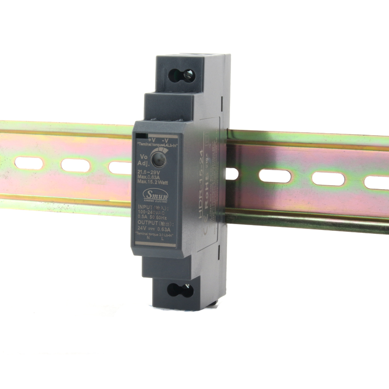
Modern panel design trends increasingly favor high-density layouts. Cabinet space limitations force engineers to rethink traditional sizing. You need compact solutions for building automation and consumer units. The HDR DIN rail power supply offers an optimal design. Its step-shape, ultra-slim profile fits effortlessly into shallow clearance cabinets. It provides industrial-grade reliability while saving precious rail inches.
Cooling and ventilation methods dictate installation spacing. Compare natural convection cooling against forced air systems. Most DIN rail units rely completely on natural convection. Heat rises through the chassis vents to cool internal heat sinks. You must leave adequate vertical spacing above and below the unit. Blocking these airflow paths guarantees premature thermal shutdown.
Implementation Risks and Common Sizing Mistakes
Ignoring concurrent operations is a frequent and dangerous design flaw. Some engineers assume actuators or valves will never fire simultaneously. Systems often trigger multiple devices during worst-case scenarios or emergency resets. The sudden current demand instantly overwhelms an undersized supply. This causes the main PLC to brownout and reset the entire machine.
Misinterpreting parallel operation capabilities ruins expensive equipment. You cannot simply wire any two power supplies in parallel to double your wattage. Units fight each other if they lack synchronization. They require specific current-sharing functions built directly into the circuit board. Always verify parallel operation support in the manufacturer datasheet before combining outputs.
Overlooking input voltage fluctuations leads to random shutdowns. Grid power quality varies wildly across industrial zones. You need a supply capable of handling wide input voltage ranges, typically 85–264VAC. This broad acceptance ensures steady output wattage despite severe AC sags or brownouts. It protects your downstream logic from unstable utility power.
Shortlisting Logic for Your DIN Rail Power Supply Selection
To finalize your DIN rail power supply selection, follow this sequential engineering checklist. It removes guesswork and standardizes your procurement process.
- Determine Output: Lock in the exact fixed or adjustable DC voltage required by your most sensitive component.
- Calculate True Wattage: Add your baseline load, verify inrush requirements, include a 30% reliability buffer, and apply the temperature derating adjustment.
- Assess Physical Constraints: Choose between standard industrial metal cases or slim plastic cases based strictly on your available DIN rail space.
- Verify Certifications: Ensure all shortlisted models carry the necessary electrical approvals (UL, CE, Class 2 power limited) required for your specific installation environment.
You ensure optimal system performance by rigorously following these steps. Skipping any phase leaves your automation system vulnerable to erratic power anomalies.
Conclusion
Choosing wattage and voltage is not merely a math exercise. It represents a complex environmental and operational calculation. Your final specification must harmonize continuous loads, thermal constraints, and physical panel limits.
Always prioritize reliability and extended MTBF over minor upfront cost savings. A robust power foundation pays for itself by preventing a single hour of machine downtime. Ensure you map out your maximum temperatures and peak startup surges before making a purchase.
Consult with a technical specialist or use a dedicated load-calculation tool to verify your exact model requirements. If you require expert validation on your next DIN rail power supply selection, reach out to experienced engineering teams who understand industrial demands.
FAQ
Q: Can I use a higher wattage DIN rail power supply than my system needs?
A: Yes. It actually improves device lifespan by allowing the internal components to run cooler. Operating at 50% capacity reduces thermal stress significantly. However, higher wattage units cost more and consume more physical space on your DIN rail.
Q: What happens if my output voltage is slightly lower than required?
A: Your connected devices may fail to power on entirely. Analog signals may skew, causing sensors to report inaccurate data. Furthermore, digital logic controllers may experience sudden brownouts, leading to random machine resets and lost production data.
Q: Are HDR DIN rail power supplies suitable for heavy industrial use?
A: They are highly reliable but typically utilized in building automation, security systems, or shallow cabinets. You must check their specific temperature and vibration ratings and compare them against heavy-duty, metal-cased units before deploying them in harsh factory environments.
Q: How much space should I leave around a DIN rail power supply?
A: You must always refer to the specific manufacturer's installation manual. Typically, units require 20-40mm of clear space above and below, and 5-15mm on the sides. This ensures proper natural convection cooling and prevents thermal overload.