
- All
- Product Name
- Product Keyword
- Product Model
- Product Summary
- Product Description
- Multi Field Search
Views: 0 Author: Site Editor Publish Time: 2026-08-26 Origin: Site


Sourcing an AC DC power supply is never just a routine commodity purchase. It represents a critical risk-management decision for your entire engineering project. A poorly specified unit quickly leads to catastrophic system failure. It creates severe compliance bottlenecks and severely delays your product's time-to-market. Reading a basic data sheet might seem straightforward at first glance. However, interpreting complex operating envelopes and uncovering hidden limitations separates reliable system integration from costly field failures. You must look past the bold marketing print to understand how the unit truly performs under heavy stress.
This guide provides a detailed, engineering-first framework for evaluating essential metrics. We will explore how to analyze critical specifications, mitigate hidden integration risks, and confidently shortlist the right manufacturing partner. You will gain actionable insights to keep your systems running smoothly in any demanding environment.
Matching top-line voltage and current ratings is only the baseline; thermal derating and transient response dictate real-world reliability.
Compliance (EMI/EMC, safety isolation) must align strictly with the end-use environment (e.g., medical vs. heavy industrial).
Evaluating an AC DC power supply supplier requires looking beyond unit cost to assess supply chain stability, testing transparency, and lifecycle support.
Total cost of ownership is heavily influenced by energy efficiency and MTBF (Mean Time Between Failures) in field conditions.
Undersizing a power unit leads to rapid thermal failure and unexpected system reboots. Conversely, oversizing drastically inflates your unit cost and physical footprint. You must balance these extremes carefully to optimize system design. Finding the exact electrical match requires analyzing both standard operation and edge-case loads.
You must evaluate your required continuous current versus peak load spikes. Many applications draw maximum power only during startup sequences or mechanical actuation. For example, spinning up a heavy motor requires a temporary current surge. Specifying common ranges, such as sourcing an AC DC power supply,12v to 48v 1a to 20a, depends entirely on capturing this maximum power draw. You must define this strict operational envelope before reviewing any vendor catalogs.
Next, decide between constant voltage and constant current or constant power modes. Most standard electronics need strict voltage regulation to prevent logic errors. However, specialized applications demand dynamic current envelopes instead. LED driving circuits or battery charging arrays require constant current operation to safely manage energy transfer. Choosing the wrong regulation mode will permanently damage sensitive downstream components.
Finally, you must consider mechanical constraints early in the design phase. Form factor selection heavily impacts overall system design. It directly dictates your airflow routing, mounting hardware, and thermal dissipation strategies. A unit might look perfect on paper but fail to fit within your chassis.
Table 1: Common Power Supply Form Factors and Applications
Form Factor | Cooling Mechanism | Typical Application | Integration Consideration |
|---|---|---|---|
Open Frame | System airflow (Forced air) | IT equipment, Consumer electronics | Requires internal chassis shielding to meet strict EMI standards. |
Enclosed | Internal fan or conduction | Industrial automation, Telecom | Larger footprint; generates internal acoustic noise if fan-cooled. |
DIN-Rail | Convection cooling | Control cabinets, Factory floors | Easy snap-on installation; requires vertical clearance for heat rise. |
Encapsulated | Conduction (Potting compound) | Harsh environments, PCB mounting | Excellent moisture and vibration resistance; heavy weight. |
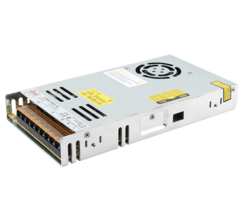
You must move past basic voltage ratings. Focus instead on the complex variables dictating long-term performance. A robust set of AC DC power supply specifications reveals exactly how a unit survives real-world electrical stress. Missing these details often results in premature field failures.
Do not rely on peak efficiency numbers alone. Manufacturers often market the absolute highest efficiency achieved under perfect conditions. You need to examine efficiency curves across 20% to 100% load variations. Units frequently drop in efficiency at lower loads, generating excess heat. Active Power Factor Correction (PFC) is equally vital. Active PFC ensures the unit draws power cleanly from the grid, preventing harmonic distortion and meeting regional regulatory limits.
Sensitive analog or digital circuits require exceptionally clean power. Ripple and noise introduce unwanted AC artifacts onto your DC line. You must define the acceptable ripple thresholds for your specific board architecture. Review how internal output filtering impacts the final signal cleanliness before integrating the unit. High ripple can cause false triggering in logic circuits or degrade audio and video signal quality.
Operating temperature heavily impacts available power delivery. A power unit rated for 100W might only deliver 60W at 50°C if it lacks forced air cooling. Always read the thermal derating curves meticulously. These curves show exactly when the internal semiconductor junctions reach their thermal limits. Ignoring derating curves guarantees overheating and subsequent system shutdown.
You must also clarify the mathematical distinction between MTBF and actual life expectancy. MTBF (Mean Time Between Failures) represents a statistical probability of failure rates across a massive population. It does not mean a single unit will last that long. In contrast, electrolytic capacitor life expectancy determines the actual physical wear-out phase under thermal stress. Capacitors dry out over time, especially in hot environments, establishing a hard limit on operational lifespan.
Failing safety or emissions compliance halts product launches instantly. You must adopt strict compliance-aware thinking from day one. Retrofitting compliance into a finished system is expensive, frustrating, and incredibly time-consuming.
Safety standards vary wildly by target industry. You must evaluate internal isolation requirements accurately based on your deployment scenario. For example, standard IT and audio-visual equipment follow the IEC 62368-1 standard. Medical devices demand much stricter IEC 60601-1 compliance. Medical standards specifically require precise Means of Patient Protection (MOPP) ratings to ensure stray currents never harm patients. Using an IT-rated supply in a medical device violates basic safety laws.
Electromagnetic Interference (EMI) and Electromagnetic Compatibility (EMC) performance matters deeply. You must evaluate both conducted emissions (noise traveling back through the power cord) and radiated emissions (noise transmitting through the air). Compare the specifications against CISPR and EN standards. Internal power supply noise easily interferes with your sensitive system electronics if improperly shielded. A noisy unit requires you to add expensive external filters to pass regulatory lab testing.
Environmental protections keep devices alive in harsh settings. Assess your requirements for conformal coating. This thin chemical layer blocks moisture and prevents conductive dust from shorting out internal traces. Check the IP (Ingress Protection) ratings against water ingress. Look for specific ruggedization guarantees against extreme vibration and mechanical shock if deploying equipment in mobile or railway applications.
Engineers routinely face significant headaches post-purchase. You can avoid these implementation realities by checking a few hidden parameters early in the design cycle. Ignoring them forces sudden redesigns.
When you power up a system, empty internal capacitors draw a massive initial current surge. This phenomenon is known as inrush current. It creates a high risk of nuisance tripping for facility circuit breakers or blowing inline system fuses. Verify the inrush current limits using an oscilloscope during initial prototyping. If the surge is too high, you must specify a unit with active inrush current limiting circuitry.
Transient response time is another critical, yet often ignored, metric. Measure how quickly the supply recovers its nominal voltage after a sudden, massive load change. This specification proves critical for devices utilizing motors, mechanical relays, or high-compute burst states. A slow transient response causes unacceptable voltage dips. These dips trigger system resets or data corruption in processors. Always match the recovery time to your load's dynamic demands.
Long cable runs in large system enclosures artificially degrade voltage before it ever reaches the load. This cable voltage drop ruins tight logic tolerances. Remote sense features compensate for this exact loss. A remote sense wire measures the voltage directly at the load terminal, rather than at the supply output. The supply then actively boosts its output to deliver the perfect voltage exactly where it matters.
To avoid integration pitfalls, watch out for these common implementation mistakes:
Ignoring minimum load requirements: Some switching supplies become unstable or shut down if you draw too little current.
Stacking supplies in parallel without current sharing: Connecting outputs blindly causes one unit to shoulder the entire load until it burns out.
Trapping ambient heat: Placing a highly efficient ac dc power supply in an unvented box still causes thermal runaway over extended periods.
Shift your focus from the standalone product to the partner behind it. Establishing strict vetting criteria helps you evaluate any AC DC power supply supplier effectively. A great product means nothing if the manufacturer cannot deliver it consistently.
Demand uncompromising manufacturing and testing transparency. Look for vendors who eagerly provide comprehensive testing reports upon request. Quality suppliers do not hide their data. You should expect to see documentation proving they subject their units to rigorous conditions.
Burn-in Testing: Operating units at full load and elevated temperatures to catch early infant mortality failures.
Thermal Cycling: Rapidly changing ambient temperatures to test solder joint integrity and material expansion rates.
Vibration Testing: Shaking the units across multiple axes to ensure heavy components do not snap off the circuit board.
Review supply chain stability and End-of-Life (EOL) policies carefully. Frame the risks of COTS (Commercial Off-The-Shelf) availability versus the risks of custom designs. Custom designs lock you into a single vendor, while COTS provides alternative sourcing options. Evaluate the supplier's EOL notification window closely. A short notice period causes sudden manufacturing halts for your own product line. Reputable suppliers guarantee availability for years and provide 12-to-18-month EOL warnings.
Assess their engineering support and customization options. Does the supplier offer direct engineering access for integration troubleshooting? Sometimes you need minor modifications to finalize your design. The ability to request custom wire harnesses, modified output voltages, or unique conformal coatings distinguishes a true partner from a simple box-pusher.
Sourcing an AC DC power supply remains a holistic, critical process. You must weigh basic electrical specifications, environmental survival constraints, and strict compliance guarantees equally. A failure in any of these three areas ruins the final product.
To move forward successfully, document your dynamic load profiles accurately before speaking to vendors. Define your environmental constraints, thermal limits, and isolation requirements in detail. Finally, request comprehensive testing data and physical evaluation samples from your shortlisted suppliers. Validating data sheet claims in your own lab prevents late-stage failures and ensures years of reliable field operation.
A: Switching power supplies use high-frequency switching to convert power. They offer high efficiency, smaller size, and lighter weight. Linear supplies rely on heavy transformers and linear regulators. They are less efficient and physically larger, but they provide exceptionally low ripple and noise. You should choose linear supplies for highly sensitive analog circuits, and switching supplies for almost everything else.
A: You should generally leave a 20% to 30% headroom buffer above your maximum expected load. This practice prevents the supply from constantly running at maximum capacity, extending component lifespan. However, you must adjust this rule based on thermal derating factors. If you operate in hot environments without forced cooling, you may need a 50% buffer.
A: A constant power range provides immense operational flexibility. It allows the supply to deliver its maximum rated power across a wider variety of voltage and current combinations. Instead of buying multiple units for different loads, you can cover diverse test cases or dynamic load profiles with a single, highly adaptable unit.
A: Active PFC aligns the input current waveform with the input voltage. This reduces harmonics and minimizes reactive power drawn from the grid. Regulatory standards often mandate active PFC for units over 75W to ensure electrical grid stability. It improves overall energy efficiency and reduces strain on your facility's wiring infrastructure.