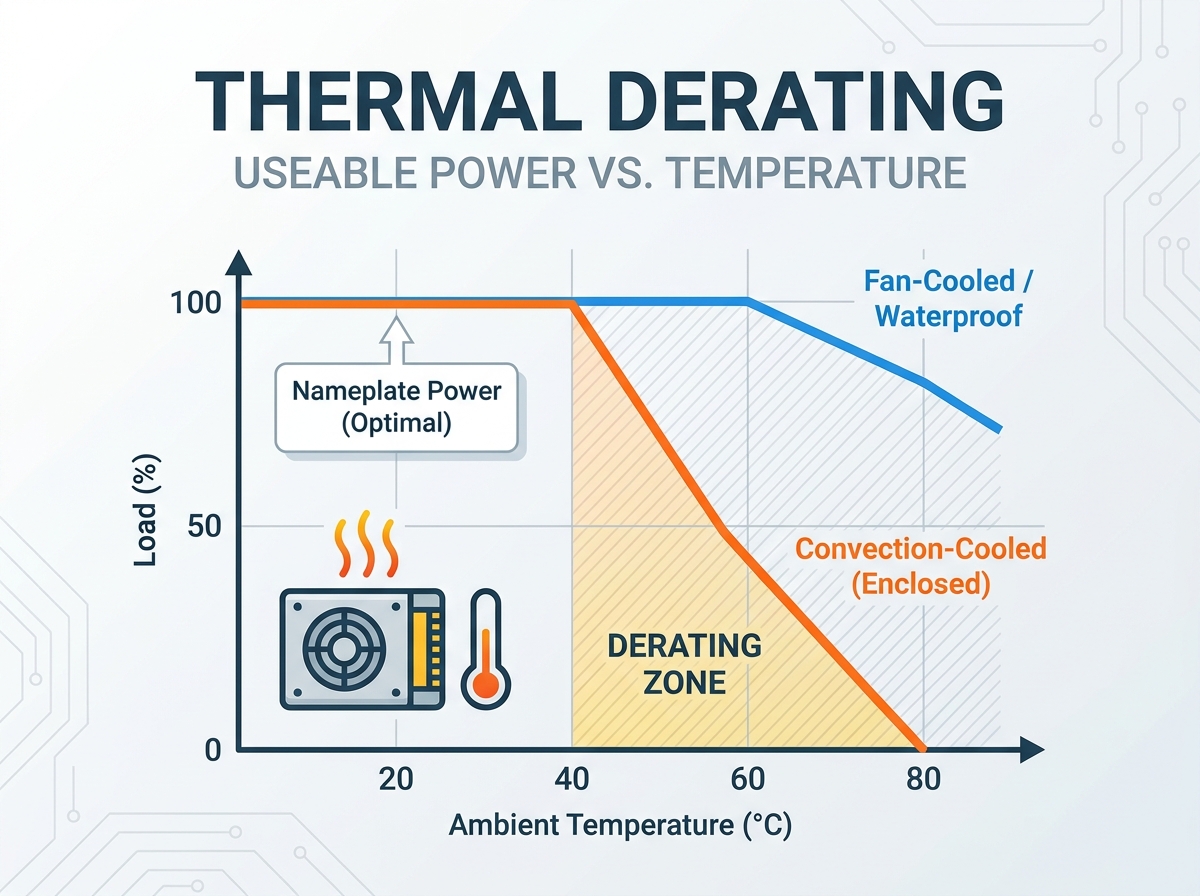
Engineers often fall into a costly trap when designing electrical systems. They assume a 500W power supply delivers a full 500W under all operating conditions. In reality, extreme field environments frequently cap safe delivery at just 250W. This massive gap exposes the common "nameplate" fallacy. Power supplies rarely operate in the ideal, climate-controlled environments used for baseline testing.
We must treat thermal performance as a critical reliability metric, not just a minor technical spec. Ignoring internal heat buildup directly causes catastrophic field failures. Heat stresses delicate components. It triggers expensive warranty claims and forces unacceptable system downtime. Every minute a machine sits idle cuts directly into operational productivity.
This article provides a transparent, step-by-step framework to solve this challenge. We will help you evaluate derating curves accurately. You will learn how to specify the exact unit required for harsh or enclosed environments. By the end, you will know exactly how to safeguard your critical hardware and build robust industrial systems.
Key Takeaways
Nameplate wattage represents optimal conditions (usually 115/230VAC input at 25°C–40°C ambient); actual output must be derated based on maximum operating temperatures.
Enclosed switching power supplies require aggressive derating without forced-air cooling due to heat trapping.
Input voltage drop directly increases internal heat generation, requiring a secondary (dual) derating calculation.
Switching to a waterproof power supply (potted/encapsulated) changes the thermal dissipation model from convection to conduction.
The Reality of Switching Power Supply Thermal Derating
Datasheet specifications frequently present a perfect-world scenario. Manufacturers test units in open air at a comfortable room temperature. Industrial applications rarely offer these conditions. As a result, the stated output power on a datasheet rarely equals the usable power in the field. Defining this performance gap remains the most important step in system design. If you pull 100% of the rated load inside a hot cabinet, the internal protection circuits will trigger. The unit will shut down completely to prevent a fire.
Enclosed power units face a unique vulnerability. We call this the enclosure penalty. Open-frame units allow air to flow freely across transformers and transistors. Conversely, a metal enclosure restricts natural convection. Heat gets trapped inside the box. Localized hotspots form around high-power switching components. Proper switching power supply thermal derating requires understanding this exact environment. You must account for the trapped heat.
We also rely on a fundamental principle known as the Arrhenius equation. This rule of thumb guides all electronic reliability calculations. Every 10°C increase in internal operating temperature generally halves the lifespan of electrolytic capacitors. Capacitors contain liquid electrolytes. Excessive heat vaporizes this liquid over time. Once the capacitor dries out, the entire power supply fails. Operating just 20°C above the ideal temperature reduces a ten-year lifespan to a mere two and a half years.
Common Mistakes in Assessing Real-World Capacity
Relying solely on the bold 100% capacity rating printed on the box.
Failing to measure the temperature inside the final installation cabinet.
Ignoring the heat generated by neighboring electronic devices.
Assuming natural convection works perfectly in tightly packed DIN rails.
Core Evaluation Dimensions for Thermal Derating
You must evaluate several core dimensions to predict unit behavior accurately. The most critical dimension is the ambient operating temperature. Many designers define "ambient" incorrectly. They measure the temperature of the factory floor. This leads to catastrophic errors. Ambient temperature strictly refers to the air immediately surrounding the power supply. Inside a sealed system cabinet, other devices generate severe heat. A motor drive or PLC easily raises the internal cabinet air to 55°C, even when the room sits at a comfortable 25°C.
Cooling methods change the derating curves dramatically. We always contrast convection-cooled units against forced-air systems. Fan-cooled units push a constant stream of cool air over the internal heat sinks. They typically maintain near 100% output up to 50°C or even 60°C. Convection-cooled units lack this active airflow. They rely entirely on hot air rising. These units often begin derating as early as 30°C or 40°C. The gap between these two technologies dictates your procurement choices.
Input voltage represents a hidden curve many engineers miss. Low-line input voltages demand a secondary derating multiplier. Consider a unit operating at 85VAC instead of 230VAC. The output load requires a specific amount of power. Because power equals voltage times current, a lower voltage forces the unit to draw significantly higher current. Higher current flowing through copper traces and inductor coils generates more heat. This independent variable forces you to derate the output further.
Thermal Performance Baseline Chart
Cooling Method
Standard Inflection Point
Typical Derating Rate
Maximum Safe Operating Temp
Convection (Fanless)
30°C - 40°C
2.0% - 2.5% per 1°C
70°C (at reduced load)
Forced Air (Built-in Fan)
50°C - 60°C
1.5% - 2.0% per 1°C
70°C - 80°C
Conduction (Cold Plate)
60°C - 70°C
1.0% - 1.5% per 1°C
85°C+ (Baseplate temp)
How to Calculate and Apply the Derating Curve for Your Application
Engineers must replace guesswork with hard mathematical models. Applying a derating curve correctly requires a systematic approach. A single miscalculation jeopardizes the entire control panel. You can ensure adequate power delivery by following four specific steps.
Step 1: Determine Peak Ambient Temperature. Do not use average temperatures. Model the absolute worst-case internal cabinet temperature. Factor in peak summer heatwaves. Add the maximum thermal load generated by every device running simultaneously inside the enclosure.
Step 2: Locate the Inflection Point. Review the specific manufacturer’s technical datasheet. Find the thermal curve graph. Look for the exact temperature where the 100% load line begins to angle downward. Standard enclosed units typically hit this inflection point between 40°C and 50°C.
Step 3: Calculate the Derating Percentage. Apply the standard linear drop defined by the graph. Most units suffer a loss of 2% to 2.5% rated power per 1°C rise above the inflection point. Multiply this percentage by the degrees over the threshold. Subtract this total from the nameplate wattage.
Step 4: Factor in Altitude. High-altitude installations mandate an extra derating layer. Thinner air contains fewer molecules. It carries away significantly less heat than dense sea-level air. Installations above 2000 meters require additional thermal derating. A common rule requires dropping the maximum ambient temperature limit by 5°C for every 1000 meters above the baseline.
Let us look at a brief example. You have a 1000W unit. The datasheet shows an inflection point at 40°C. The curve drops 2% per degree. Your cabinet hits 55°C. You are 15 degrees over the limit. Multiply 15 by 2% to get a 30% reduction. The unit loses 300W of capacity. Your 1000W unit only safely supplies 700W. If your load requires 800W, the unit will overheat.
Enclosed vs. Waterproof Power Supply: Choosing the Right Thermal Architecture
Selecting the right physical format directly influences long-term survival. The physical architecture dictates how heat escapes the internal circuitry. A traditional Enclosed Switching Power Supply provides basic protection against accidental contact. The perforated metal cage allows some natural air currents to pass through. We find these units perform best in climate-controlled environments. They suit vented system cabinets perfectly. They also work well in applications where periodic fan maintenance is acceptable.
However, traditional enclosures face severe limitations in dirty environments. They are highly susceptible to dust buildup. Dust acts as a powerful thermal insulator. A thin layer of factory grime covers the internal heat sinks. This restricts natural convection entirely. Over time, the internal temperatures rise higher and higher. Thermal performance worsens steadily until the unit burns out prematurely.
Switching to a Waterproof Power Supply drastically alters the thermal dynamics. Manufacturers build these units using encapsulated or potted designs. They inject a specialized epoxy or silicone resin into the casing. This compound hardens and completely surrounds the electrical components.
These potted units dominate harsh environments. They excel in outdoor enclosures and fanless system requirements. The thermal advantage is structural. Air gaps inside traditional units act as poor conductors. Thermal potting compound eliminates these internal air gaps. It conducts heat directly from the hot MOSFETs to the external metal chassis. You can mount these units against a larger external heat sink. This fundamentally alters the derating curve. The transition from convection cooling to direct conduction cooling improves long-term reliability tremendously.
Comparison Table: Enclosed vs Waterproof Thermal Architectures
Feature
Standard Enclosed Architecture
Waterproof (Potted) Architecture
Heat Transfer Mode
Air convection (natural or forced)
Direct thermal conduction
Environmental Vulnerability
High (Dust acts as a thermal blanket)
Low (Sealed against dust and moisture)
Fan Requirement
Often required for high wattage
Completely fanless operation
Typical Derating Start
Drops sharply after 40°C - 50°C
Maintains capacity up to 60°C+ via cold plate
Procurement Risks and Shortlisting Logic
Evaluating datasheets requires healthy skepticism. Procurement teams face significant risks when sourcing electrical components. Datasheet manipulation occurs frequently in this industry. Some manufacturers spec their 100% load rating at highly unrealistic temperatures. They might claim a 600W rating at a 20°C ambient temperature. We rarely see 20°C inside an active industrial control panel. Warn buyers against shortlisting units based purely on these headline numbers. Always check the fine print in the thermal graphs.
Engineers sometimes counter poor thermal performance using an "oversizing" strategy. They buy a massive 1000W supply to reliably run a 500W load at 65°C. This brute-force method works technically, but it introduces severe trade-offs. You must weigh the spatial and upfront budget impacts. A 1000W unit consumes valuable DIN rail space. It forces you to buy larger, bulkier cabinets. Investing in better system-level thermal management often proves smarter. Adding a cabinet cooling fan or a heat exchanger allows you to buy the appropriately sized power unit.
You need concrete next-step actions before finalizing bulk orders. Do not rely on assumptions. We recommend requesting MTBF (Mean Time Between Failures) data calculated at your specific derated temperatures. A unit might show a great MTBF at 25°C, but fail rapidly at 55°C. Conduct thermal chamber validation testing on sample units. Place the power supply under full target load inside an oven. Measure the actual heat generated. This hands-on validation catches thermal failures before they reach the factory floor.
Conclusion
Thermal derating stands as a non-negotiable step in power supply specification. Ignoring heat buildup guarantees premature failure and systemic downtime. The nameplate wattage only tells a fraction of the story. You must dig into the performance curves to understand actual capacity.
Base your final procurement decisions entirely on the worst-case operational environment. Assume the cabinet will run hot. Assume natural airflow will face restrictions. By designing for the harshest conditions, you ensure continuous, stable power delivery. Never let an attractive headline specification override basic thermal physics.
Take immediate action on your next design cycle. Review technical datasheets carefully to find the true inflection points. Calculate the precise derating percentages for both temperature and altitude. Finally, consult extensively with thermal engineering teams to align your power supply selection precisely with your enclosure design.
FAQ
Q: At what temperature does an enclosed switching power supply typically require derating?
A: Most standard convection-cooled enclosed units require derating starting at 40°C or 50°C. Once the ambient temperature inside the cabinet exceeds this specific threshold, the unit typically loses about 2% to 2.5% of its rated capacity per degree.
Q: Does input voltage affect thermal derating?
A: Yes. Operating at the lower end of the input voltage range (such as 85-115VAC) reduces internal efficiency. The unit draws more current to deliver the same power. This generates much more internal heat, requiring a secondary derating calculation compared to operating at a stable 230VAC.
Q: Why might a waterproof power supply have better thermal performance than a standard enclosed unit?
A: Waterproof units are typically filled with a heat-conductive epoxy or silicone compound called potting. This material transfers heat directly from internal hot components to the outer metal casing. This direct conduction makes them highly effective in fanless, high-temperature environments where air convection fails.