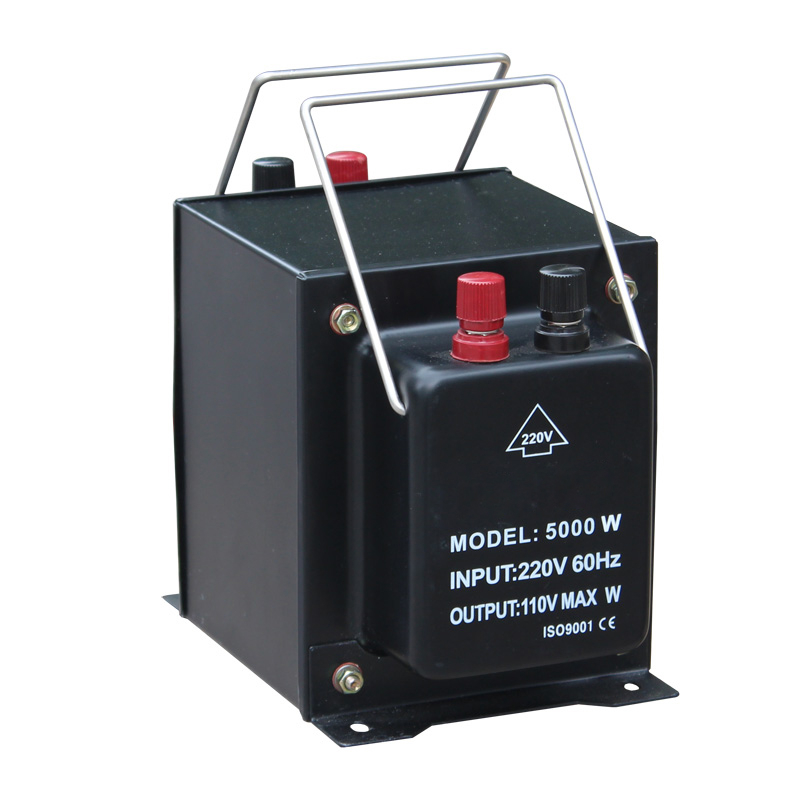
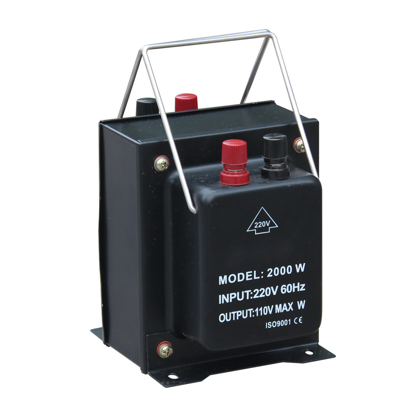
A control transformer isolates logic from mains. It steps 480V or 400V down to 120V or 24V and breaks the ground path to sensitive controllers.
Inrush sets the size, not the holding load. Contactor coils draw five to ten times their sealed current for a few cycles.
Sum sealed VA first, then the worst case. The second number usually decides the kVA rating you order.
Voltage dip is the acceptance test. Secondary voltage must stay above the contactor pick-up threshold during the largest simultaneous pull-in.
Primary taps correct site voltage. Match the tap to the measured incoming voltage instead of trusting the nameplate value.
Protect both sides. Secondary fuses protect wiring; primary protection covers the transformer and must ride through inrush.
Introduction
A control panel transformer is an essential magnetic component designed to step down high industrial distribution voltages to safer, lower levels (typically 120V or 24V) required by relays, contactors, and PLCs. Proper kVA sizing is critical to ensure voltage stability during the high inrush currents characteristic of inductive control loads.
In industrial automation, the main incoming power to a machine is usually a high voltage, such as 480V or 400V three-phase, which is necessary for driving large motors and heavy loads. However, the delicate logic circuits, human-machine interfaces (HMIs), and electromagnetic switching devices inside the control cabinet cannot operate at these hazardous voltages. They require a localized, stable, and isolated low-voltage power source. This is exactly where the control transformer acts as the crucial bridge, safely isolating the control circuitry from the noisy and dangerous primary mains while delivering the precise voltage required for reliable logic execution and switching operations.
What is a Control Panel Transformer?
Isolation and Voltage Step-Down Functions
At its core, a transformer control panel component is a specialized isolation transformer engineered specifically for the harsh electrical environment of industrial cabinets. Unlike general-purpose lighting or distribution transformers, it is constructed with excellent voltage regulation in mind. Its primary function is to step down the facility's high AC voltage (e.g., 480VAC) to a standardized control voltage (e.g., 120VAC or 24VAC). The physical separation between the primary and secondary windings provides vital galvanic isolation. This isolation prevents ground loops, limits the propagation of common-mode noise from the heavy machinery back into the sensitive logic controllers, and significantly enhances operator safety by creating a localized, ungrounded (or separately derived) control circuit within the panel.
Handling High Inrush Currents from Inductive Loads
The defining characteristic that separates these devices from standard transformers is their ability to handle severe inrush currents without catastrophic voltage drop. Control cabinets are densely packed with highly inductive loads: the electromagnetic coils of motor starters, contactors, solenoids, and large relays.
When these devices are initially energized, their magnetic cores are not yet magnetized, resulting in a momentary surge of current that can be 5 to 10 times higher than their steady-state holding current. A properly designed control transformer possesses a low impedance and robust magnetic core, allowing it to supply these massive, instantaneous current spikes while maintaining the secondary voltage within a tight tolerance (usually preventing a drop of more than 5-10%). If the voltage dips too low during this inrush period, contactors may "chatter" or fail to pull in, leading to erratic machine operation and premature contact wear.
Table 1: Control Transformer Against a General-Purpose Transformer
How to Calculate Required kVA with Overload Margins
Determining Steady-State (Sealed) VA Requirements
The first step in properly sizing control panel transformers is calculating the total steady-state load. This is the baseline power required when the machine is running normally and all necessary contactors and relays are energized and holding their positions.
To find this, engineers must sum the "sealed VA" (Volt-Amperes) ratings of every component connected to the transformer's secondary. This includes the holding VA of all contactor coils, the continuous draw of indicator lights, PLC power supplies, timers, and small cooling fans. It is crucial to review the datasheets for every device on the control circuit to ensure an accurate tally. If the continuous load exceeds the transformer’s continuous rating, the unit will overheat, degrading the insulation and significantly shortening its operational lifespan.
Factoring in Maximum Inrush VA
Calculating the steady-state load is not enough; the transformer must be sized for the worst-case inrush scenario. Engineers must identify the specific moment in the machine's operating cycle that demands the highest simultaneous inrush current. This usually occurs during startup, when the largest motor contactor pulls in, perhaps simultaneously with several smaller relays. You must calculate the total "inrush VA" for this specific combination of components and add it to the sealed VA of all other devices that are already energized at that moment.
Once this maximum total VA is determined, consult the transformer manufacturer's inrush regulation curves. You must select a kVA rating that can deliver this peak inrush demand while ensuring the secondary voltage does not drop below the minimum pick-up voltage of the contactors (typically 85% to 90% of nominal). Simply adding a generic 20% margin is often insufficient and can lead to unreliable machine startups.
Table 2: Sizing Worksheet Sequence
Step
Quantity to collect
Source
Decision it drives
1
Sealed VA of every coil and device
Device datasheets
Continuous rating
2
Worst-case simultaneous inrush VA
Contactor tables
Peak demand
3
Minimum pick-up voltage
Contactor datasheet
Allowable dip
4
Ambient inside the cabinet
Panel thermal survey
Derating
5
Selected kVA and tap
Manufacturer curves
Final order
Sizing check: kVA = total sealed VA ÷ 1000. Voltage dip (%) ≈ (inrush VA ÷ rated VA) × impedance (%), then compare the result with the manufacturer's inrush regulation curve.
Illustrative method only; not a product specification.
Primary and Secondary Voltage Tap Selection Guide
Utilizing Primary Taps for Voltage Variations
Industrial power grids are rarely perfect; the actual voltage supplied to a facility can fluctuate significantly based on location, time of day, and heavy loads starting elsewhere on the grid. To compensate for these variations, high-quality panel transformers are equipped with multiple primary voltage taps. For instance, a transformer rated for 480V primary might have taps for 460V and 500V, or specific "+5%" and "-5%" terminals.
During commissioning, the electrician must measure the actual incoming line voltage at the machine disconnect. If the facility voltage consistently runs high (e.g., 505V), the incoming power wires should be landed on the +5% tap. This ensures that the secondary voltage remains precisely at the target 120V, preventing the control components from being over-voltaged, which leads to excessive coil heating and premature failure.
Dual-Voltage Secondaries and Fuse Protection
Flexibility is also critical on the secondary side. Many industrial transformers feature dual-voltage secondary windings, commonly offering both 120VAC and 24VAC (or 240V/120V configurations). This allows a single transformer to supply the standard 120V for legacy contactors and large solenoids, while simultaneously providing an isolated 24V circuit for modern PLCs, safety relays, and low-voltage sensors.
Regardless of the voltage utilized, proper overcurrent protection is absolutely mandatory. Fast-acting fuses or dedicated miniature circuit breakers (MCBs) must be installed on the secondary side to protect the control circuit wiring from short circuits, and on the primary side to protect the transformer itself from massive overloads. The sizing of these fuses must strictly adhere to local electrical codes (such as NEC or IEC) and must be carefully coordinated with the transformer's inrush characteristics to prevent nuisance tripping during machine startup.
Conclusion
The reliable operation of any industrial automation system hinges directly on the stability of its control voltage. An undersized or improperly specified control panel transformer is a hidden liability that can cause intermittent contactor chatter, logic resets, and premature component failure due to excessive voltage droop during switching transients.
By meticulously calculating both the steady-state sealed VA and the critical maximum inrush VA, and by intelligently utilizing primary taps to match actual facility voltages, engineers secure a robust and stable power foundation for their control cabinets. Where a panel needs only a low-voltage rail, the control transformer category page groups the sizes that fit inside a machine cabinet.
Q: Why does a control transformer need a low impedance?
A: Because contactor coils draw a surge of current when first energized, and a high-impedance winding would let the secondary voltage collapse during that surge. Low impedance keeps the dip inside the tolerance the coils need to pull in and hold.
Q: How do I calculate sealed VA?
A: Add the holding VA of every contactor coil, relay coil and solenoid, then add the continuous draw of indicator lights, PLC supplies, timers and fans. Use the datasheet figure for each device rather than a rule-of-thumb estimate, since coil burden varies widely.
Q: What happens if the transformer is undersized?
A: The unit runs hot, the insulation ages faster and the secondary voltage sags during inrush. In practice the first symptom is contactor chatter or a PLC that resets when a large starter pulls in, which is often misdiagnosed as a logic fault.
Q: Should I always add a 20% margin?
A: A flat margin is a rough starting point, not a sizing method. The real requirement is that the secondary stays above the pick-up threshold during the worst simultaneous inrush, so the calculation has to use the inrush curve rather than a fixed percentage.
Q: Can a 24V power supply replace the transformer?
A: For logic and sensors it can, because a switched-mode supply regulates better and is smaller. It does not provide the same isolation or inrush behavior for contactor coils, so many panels keep the transformer for coils and add a DIN rail 24V supply for electronics.