A DIN rail redundancy module sits between two or more DIN rail power supplies and the load, combining their outputs through decoupling diodes or equivalent circuitry so that a single failed supply cannot drag the shared rail down. It is the component that turns "two power supplies" into an actual redundant feed, and it is the part most often left out of a bill of materials. This guide covers what the module does, how 1+1 and N+1 differ in sizing, how to match the module to the supplies on the rail, and the wiring and monitoring details that decide whether the installation behaves as designed.
Key Takeaways
Parallel wiring is not redundancy. Without decoupling, a failed supply becomes a load on the healthy one and pulls the rail down with it.
1+1 and N+1 differ in sizing, not in principle. Both need a module between the supplies and the load.
The module is rated for the current it carries. Size it for the full load current, not for the current of a single supply.
Voltage drop is a real budget item. It reduces the margin you calculated between the supply output and the load's minimum input.
Match the module's voltage range to the DC bus. Modules are published for 12V, 24V and 48V DC systems.
Plan fault indication at the same time. A redundant system without signalling converts an unnoticed failure into an outage.
Why DIN Rail Power Supplies Need Redundancy Modules
What actually fails in a DIN rail supply?
The components that age are the ones carrying the stress: the electrolytic capacitors on the output, the fan on higher-power formats, and the input rectifier. A published example in this portfolio states an operating temperature of −25 °C to +50 °C with derating above 50 °C, which is a reminder that the unit runs closest to its limits in exactly the sealed cabinets that are hardest to service. Failure is therefore a scheduled probability, not an accident, and the design question is what the system does when it happens. The broader decision logic is covered in our guide to when a DIN rail power supply needs N+1 redundancy.
What does a redundancy module do that parallel wiring does not?
It isolates the outputs. When two supplies are wired directly in parallel, a shorted output inside one of them becomes a low-impedance path across the rail, and the healthy supply delivers its entire current into the fault instead of into the load. Decoupling prevents that reverse current path, so a failed unit can be removed while the system continues to run. The module also typically presents a common output terminal, which simplifies the load wiring compared with paralleling at the terminals of each supply.
1+1 versus N+1
How do the two topologies differ in sizing?
In 1+1, two supplies each cover the full load, so either one alone can hold the rail. That is the usual answer for a single critical load because it tolerates one failure with no reduction in capacity. In N+1, N supplies share the load and one additional unit provides the spare, which is the pattern for a larger installation where the load is distributed across several converters and where losing one unit still leaves every load fed. Both are published as supported configurations for the 20A DIN rail redundancy module in this portfolio, which operates from 12V, 24V or 48V DC.
What current rating does the module need?
Size it for the load current it must carry continuously, then confirm that the figure applies at your ambient. In a 1+1 arrangement with a 20A load, each supply is rated for 20A and the module carries 20A in normal operation. In an N+1 arrangement with four 10A supplies feeding a 30A load, the module carries 30A continuously even though no single supply exceeds 10A. The mistake to avoid is sizing the module from the supply current rather than from the load current — that habit works in 1+1 by coincidence and fails immediately in N+1.
Table 1: 1+1 versus N+1
Dimension
1+1
N+1
Supplies used
Two, each sized for the full load
N sharing the load, plus one spare
Load per supply in normal operation
Shared, either unit can carry all
Shared across N units
Behaviour on one failure
Load continues, full capacity retained
Load continues without interruption
Typical application
Single critical load
Larger installations with distributed loads
Module sizing basis
Full load current
Full load current
Practical constraint
Two identical supplies and matched wiring lengths
Load sharing across all units, plus clear fault indication
Configuring the Redundancy Pair
How do you match the module to the supply voltage?
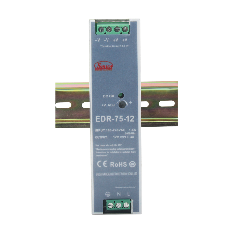
Match the module's published DC range to the voltage of the supplies it serves. Modules are published for 12V, 24V and 48V DC systems, which covers the common industrial DIN rail families. The DIN rail power supply range includes supplies at those voltages, and the EDR Series economical slim DIN rail supplies publish 12V, 24V and 48V outputs across 75W, 120W and 150W with an input range of 90–264 VAC or 120–370 VDC at 47–63 Hz. The voltage match is therefore made before the current rating is considered. Confirm the module's published range covers the supply's output window, not just its nominal figure.
What voltage drop does the module introduce?
Every decoupling element introduces a forward voltage drop, and it comes out of the margin between the supply output and the load's minimum acceptable input. A 24V system with a supply set to 24.0V and a module dropping 0.25V presents 23.75V at the load, which is usually acceptable and occasionally is not — for example when a sensor or a relay has a tight minimum input specification. Add the drop to your budget in the same step where you calculate cable losses, rather than discovering it at commissioning.
How do you wire the monitoring signals?
Both the supplies and the module typically provide status contacts, and the useful configuration is one that lets a remote operator distinguish three states: everything healthy, one supply failed but the load still fed, and the rail below tolerance. Wire the supply status contacts so that a single failure raises a distinct alarm rather than a generic one, and route the alarm to a channel somebody actually reads. A redundancy module that fails silently has delivered redundancy on paper for as long as the second supply lasted.
Table 2: DIN rail supply families and published ratings
Series
Published wattage
Published output
Published detail
HDR Series
15W to 150W
5V, 12V, 15V, 24V, 48V DC
Ultra-slim format, 85–264 VAC input
DR Series
30W, 45W, 60W
5V, 12V, 24V, 48V
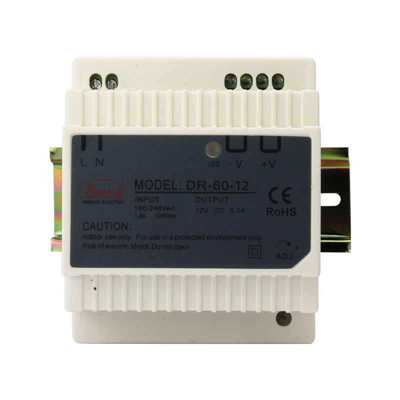
Published models DR-60-12 at 0–5A, DR-60-24 at 0–2.5A, DR-60-48 at 0–1.25A, 60W each
EDR Series
75W, 120W, 150W
12V, 24V, 48V
Input 90–264 VAC or 120–370 VDC, 47–63 Hz; efficiency 85.5% to 88.5% by model
TDRT Series
480W, 960W
24V
Three-phase input; TDR-480 at 20A, TDR-960 at 40A
RSP-320
320.4W, 321W, 321.6W
12V, 15V, 24V
Input 88–264 VAC or 124–370 VDC; panel or rail mounting
RSP-2000
2000W constant
24V–150V adjustable, ±3%
Panel mount with optional DIN rail adapter
Ratings above are quoted from published series and model tables. Confirm the exact model, input window and mounting option on the datasheet before ordering.
Load Sharing and Fault Indication
Do the supplies share the load equally?
Only approximately, and not by design. Published DIN rail supplies in this portfolio regulate their own output and do not include a current-sharing bus, so two units with slightly different output voltages will not split the load evenly — the unit set marginally higher carries more. The DR Series 30W to 60W DIN rail supplies publish independent output regulation per model, so the split follows from the voltage setting rather than from a controlled sharing function. That is acceptable in a redundant system because the design does not depend on equal sharing, but it does mean the load per unit cannot be assumed to be half the total. Leave headroom above the continuous rating rather than sizing the pair so that perfectly equal sharing would be required.
What should the monitoring system watch?
Three quantities, in this order of usefulness: whether each supply is reporting healthy, whether the rail voltage stays above the load's minimum, and whether the ambient inside the cabinet has risen beyond what the derating curve allows. A published example in this portfolio states hold-up time of 60 ms at 230 VAC and 12 ms at 115 VAC at full load, which is the kind of figure that becomes relevant when the monitoring system records a brief input interruption and the engineer needs to know whether the supply rode through it.
Sizing Worked Example: A 24V Cabinet With a 20A Load
Consider a control cabinet with a critical 24V load drawing 20A continuously, where a single failure must not interrupt operation.
Step 1 — Confirm the load current. 20A continuous at 24V, which is 480W.
Step 2 — Choose the topology. With one critical load, 1+1 is the straightforward answer: two supplies, each rated to carry the full 20A.
Step 3 — Derate for the internal ambient. Read each supply's derating curve at the measured cabinet temperature. If the curve reduces the usable output at that ambient, select the next rating up rather than assuming the nameplate figure is available.
Step 4 — Size the redundancy module. The module must carry the full load current of 20A continuously, so a module published at 20A for 12V, 24V or 48V DC systems matches this duty.
Step 5 — Budget the voltage drop. Subtract the module's published drop from the supply output and confirm the result still exceeds the load's minimum input specification with margin.
Step 6 — Wire the status contacts. Route each supply's status signal so that a single failure raises a distinct alarm, then test the alarm by removing one supply's input.
Illustrative method only; not a SMUN product specification.
Commissioning Checklist
Both supplies set to the same output voltage, measured at the load terminals rather than at the supply.
Module current rating verified against the full load current, not against a single supply's rating.
Voltage drop measured at full load and compared against the load's minimum input specification.
Cable lengths matched between the supplies and the module, so that wiring resistance does not bias the sharing.
Failure tested deliberately — remove one supply's input during commissioning and confirm the load continues.
Alarm verified by the same deliberate failure, so that the monitoring system is known to work before it is needed.
Conclusion
A DIN rail redundancy module is what converts two power supplies into a redundant feed. Without it, parallel outputs share a common fault path, and a failure in one unit takes the rail down with it. With it, the failed unit can be isolated and replaced while the load continues to run — which is the entire point of specifying redundancy in the first place.
The configuration itself is simple once two numbers are settled: the full load current, which sizes the module, and the module's published voltage drop, which comes out of the margin between the supply output and the load's minimum input. Sizing the module from a single supply's current is the error that looks correct in a 1+1 arrangement and breaks immediately when the same logic is applied to N+1.
Before requesting a quotation, confirm the DC bus voltage, the full load current, the topology you intend to use, the derating curve at your measured cabinet ambient, and whether fault signalling is part of the scope. Those five answers define the module and the supplies together.
FAQ
Q: Can I just connect two power supplies in parallel for redundancy?
A: Not without decoupling. Directly paralleled outputs create a common fault path, so a shorted output in one supply draws current from the healthy one instead of being isolated. A redundancy module provides that decoupling and gives you a single output terminal for the load.
Q: How do I size the redundancy module?
A: From the full load current it must carry continuously, not from the rating of an individual supply. A 1+1 pair feeding a 20A load needs a module rated for 20A; an N+1 group of four 10A supplies feeding a 30A load also needs a module rated for 30A.
Q: Does the module cost me output voltage?
A: Yes — the decoupling element introduces a forward voltage drop that reduces the voltage reaching the load. Budget it in the same step as cable losses, and confirm the result still exceeds the minimum input specification of the most sensitive load in the cabinet.
Q: Do the two supplies share the load equally?
A: Approximately, not exactly. Published DIN rail supplies regulate their own output without a current-sharing bus, so the unit set marginally higher carries slightly more. Redundancy does not depend on equal sharing, but leave headroom above the continuous rating rather than sizing the pair assuming a perfect 50/50 split.
Q: What is the difference between 1+1 and N+1 in practice?
A: In 1+1 two supplies each cover the full load, so either can hold the rail alone. In N+1 the load is shared across N units with one spare, which suits larger installations with distributed loads. Both require a redundancy module, and in both cases the module is sized by the load current.