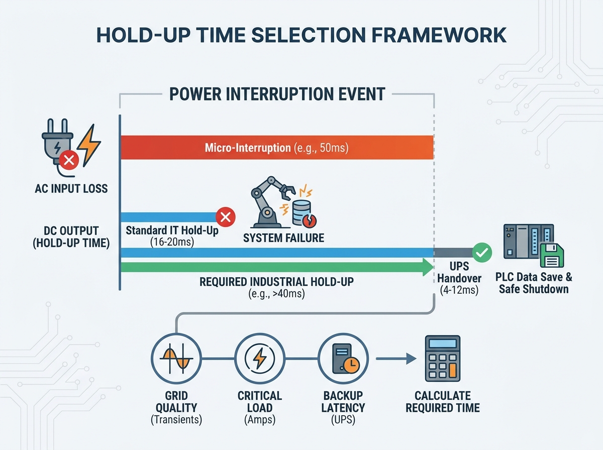
Under-specifying this critical parameter leads to nuisance tripping, data corruption in programmable logic controllers (PLCs), and uncontrolled mechanical stops. Over-specifying it inflates enclosure sizes and balloons project budgets unnecessarily. Standard IT-grade units typically default to a 16–20ms delay. Industrial environments face much harsher realities. They experience frequent grid transients. They endure heavy inductive load switching on factory floors. They also must meet far stricter regulatory compliance requirements.
We built this guide to give panel builders and system engineers a clear, evidence-based framework. You will learn how to accurately calculate, evaluate, and source the correct energy buffer for your control equipment. We will explore everything from grid stability to capacitor degradation. You can stop guessing and start engineering more resilient automated systems.
Key Takeaways
Standard 20ms power supply hold up time is often insufficient for industrial automation involving PLCs or robotic controllers requiring safe shutdown sequences.
Hold-up requirements are dictated by three factors: grid quality, critical load power draw, and the latency of secondary backup systems (e.g., UPS or redundant feeds).
Extending hold-up time physically requires larger bulk capacitors, which impacts the dimensional footprint and thermal management of an Enclosed Power Supply.
Compliance with UL 508A and specific machinery directives requires verifiable mitigation of power interruption risks, making documented hold-up capabilities a strict procurement filter.
System-Level Impact of Micro-Interruptions on Control Panels
Modern industrial facilities run on highly volatile electrical grids. Massive motors, stamping presses, and overhead cranes operate simultaneously. These machines draw immense inrush currents during startup. This suddenly depresses the local bus voltage. Such events create frequent voltage sags, brownouts, and micro-interruptions. These interruptions typically span 10ms to 50ms. Most factory personnel never notice them. However, sensitive electronics feel every single drop. Control panels bear the brunt of these power quality issues.
Failing to account for these micro-interruptions triggers severe operational consequences. When the energy buffer runs empty before a transient passes, downstream components crash. You face several immediate dangers:
PLC logic resets occur instantly. This causes a complete loss of volatile memory data.
Safety relays unexpectedly de-energize. This creates massive safety hazards around moving machinery.
Actuator synchronization fails completely. Operators must perform tedious manual system reboots.
A correctly specified energy buffer prevents these disasters. It ensures the DC bus voltage remains inside the strict operational tolerance of all downstream components. The system stays alive just long enough. It bridges the gap until AC power stabilizes. Alternatively, it provides enough time for the controller to execute a safe, controlled shutdown sequence. You maintain full control over the machine state.
Core Evaluation Framework for Sourcing Hold-Up Time
1. Calculate the Critical Load Draw
Engineers often make a critical mistake during system design. They base their buffer calculations on the maximum wattage rating of the AC/DC unit. You must base this calculation on the actual continuous draw of critical components. Identify your PLCs, human-machine interfaces (HMIs), and safety relays. Sum up their precise power consumption during a typical failure event.
Operating at a reduced capacity dramatically changes the math. An assumption check proves this principle clearly. Operating a unit at 50% load effectively extends the buffer duration. It often doubles the duration compared to running at 100% full load. You can leverage this inverse relationship to buy extra milliseconds without changing hardware.
2. Determine Required Bridge Time
You must define exactly what the system needs to survive. Different operational goals require completely different timing strategies. Consider these three common scenarios:
Transient Bridging: You only need to survive localized factory grid sags. Look for ratings between 20ms and 40ms.
UPS Handover: Standard offline or line-interactive UPS systems take time to switch over. They typically require 4ms to 12ms. The primary AC/DC unit must comfortably bridge this exact gap.
Safe Shutdown Sequence: Certain applications must save machine state data. Calculate the exact milliseconds the controller needs to write to non-volatile memory. This process can range anywhere from 20ms to well over 50ms.
Bridge Time Requirement Chart
Application Scenario
Expected Interruption
Recommended Buffer Duration
Standard IT Server Handoff
4ms to 10ms
16ms to 20ms
Heavy Machinery Grid Sags
10ms to 30ms
35ms to 50ms
PLC State Saving (EEPROM)
20ms to 50ms
60ms+
3. Account for Capacitor Aging and Derating
Implementation risk remains high even after perfect calculations. This metric relies entirely on internal electrolytic capacitors. These physical components degrade over time. High ambient temperatures severely accelerate this degradation process. Electrolytic fluid slowly dries out inside the aluminum cans. This physically reduces energy storage capacity.
We strongly recommend factoring in a 10-20% safety margin. A specification reading 20ms on day one will not remain 20ms forever. It may degrade to 16ms after five years. This happens frequently inside high-heat industrial enclosures. Always engineer for the end of the product lifecycle.
Navigating Hardware Trade-Offs and Form Factors
Thermal and Dimensional Constraints
Basic physics governs electrical energy storage. Increasing the buffer duration strictly requires larger primary capacitors. You cannot cheat this physical law. This fundamental reality severely limits product miniaturization. Manufacturers must use larger cans to hold more charge.
Panel builders must carefully verify physical dimensions. When specifying an Enclosed Power Supply, you must check the data sheet closely. Extended-buffer models demand significantly larger metal housings. You must verify if these increased dimensions violate DIN-rail limits. They might also crowd existing backplate space constraints.
Cooling impacts present another major hurdle. Larger capacitors inside tightly packed enclosures restrict natural airflow. The internal thermal dynamics change entirely. This restriction potentially necessitates active cooling fans. If you cannot add fans, you must apply aggressive thermal derating to the entire panel.
Add-on Buffer Modules vs. Integrated Solutions
Engineers must choose between building the capability inside the unit or adding it externally. Both approaches offer distinct advantages.
Integrated solutions keep panel design simple. You source an Industrial Switching Power Supply featuring a custom high-capacity buffer out of the box. Some units offer 40ms or more natively. This approach works best for fixed, known constraints. It reduces wiring complexity. It also saves precious DIN-rail width.
Buffer modules provide extreme scalability. These external DIN-rail capacitor banks store dedicated DC energy. They can extend survival time to several hundred milliseconds. This approach works best for scaling existing panels. You use them for extreme reliability scenarios. You do not need to redesign or replace the primary AC/DC unit.
Compliance and Standard Complexities (UL 508A Focus)
Navigating regulatory realities requires precise documentation. The UL 508A standard governs Industrial Control Panels. It does not dictate a universal millisecond value for energy buffering. However, it mandates overall safe operation. The standard explicitly requires protection against uncontrolled machine restarts.
Risk assessment alignment simplifies your engineering process. You must follow automated machinery directives like NFPA 79 and IEC 60204-1. These directives focus heavily on supply interruptions and dangerous voltage drops. Sourcing components backed by documented, tested buffer times makes compliance much easier. You can hand the inspector a verified performance curve. This proves you mitigated the interruption risks.
You must also maintain a high trust factor regarding manufacturer claims. Beware of vendors playing tricks on spec sheets. Many manufacturers boldly state impressive buffer times based on a nominal 230Vac input. They deliberately hide the poor performance at 115Vac. Stored energy scales with the square of the input voltage. A unit running at 115Vac often delivers half the time compared to 230Vac. Always demand exact performance curves for your specific target market voltage.
Shortlisting Logic & Next-Step Actions
You need a systematic approach to narrow down your procurement options. Follow this logic sequence to guarantee reliable panel performance.
Step 1: Audit Target Environment. Measure typical grid sags in the installation facility. Use an oscilloscope to capture the true depth and duration of local voltage drops. You must also identify the exact UPS handover times if a backup system exists.
Step 2: Map the Load. Calculate the exact DC wattage required to keep safety systems alive. Include logic controllers and network switches. Exclude non-critical heavy loads. Do not include heaters or non-essential motors in this specific calculation.
Step 3: Review Spec Sheets Skeptically. Cross-reference the stated metrics against your operating realities. Check the input voltage difference carefully (115V vs 230V). Adjust the expected duration based on your exact load percentage (100% vs 50%).
Step 4: Prototype and Test. Never trust the math alone. Prior to full procurement, simulate an input power loss. Use a programmable AC source. Verify the PLC state retention matches your earlier mathematical calculations perfectly.
Conclusion
Selecting this vital metric is never a generic checkbox exercise. It remains a critical engineering calculation. You must constantly balance dynamic load requirements, physical enclosure space, and overall system resilience. Every micro-interruption tests the limits of your panel design.
Defaulting to standard IT parameters introduces unacceptable risk in industrial automation. Engineers must prioritize AC/DC units featuring transparent performance curves. You must demand data showing performance at maximum operational temperatures. Only then can you guarantee true reliability.
Audit your current control panel's critical load requirements today. Map out exactly what components must survive a 30ms sag. Consult a technical sales engineer to evaluate high-capacity units or external buffer modules for your very next build.
FAQ
Q: Does input voltage affect power supply hold up time?
A: Yes. The duration is directly tied to the energy stored in the primary capacitor. This storage capacity is a mathematical function of the input voltage. An industrial unit will generally provide a much longer duration when operating at 230Vac compared to 115Vac. Always check the official spec sheet for your specific input voltage.
Q: Can I increase hold-up time by using a power supply with a higher wattage rating than I need?
A: Yes, this is a very common engineering workaround. The duration acts inversely proportional to the applied load. Running a 480W unit at only 240W effectively cuts the load to 50%. This maneuver will roughly double the effective buffer time compared to running the unit at full capacity.
Q: What is the difference between hold-up time and ride-through time?
A: Engineers often use them interchangeably in practical settings. However, a technical distinction exists. Hold-up time strictly refers to the time the output voltage remains regulated after AC input drops to zero. Ride-through time often refers to the broader system's ability to survive a transient event without any operational disruption.
Q: Are external buffer modules better than buying a power supply with a long hold-up time?
A: It entirely depends on your specific requirement. If you only need to bridge a 30ms gap, an integrated unit is more cost-effective and saves physical space. If you need 200ms or more to execute a complex mechanical shutdown, external capacitor-based buffer modules become the only practical solution.