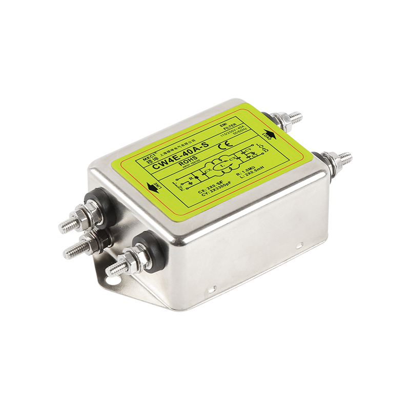
A filtered inlet is a boundary device. It pairs an IEC 60320 inlet with a suppression network so noise is stopped at the enclosure wall.
Insertion loss is frequency-specific. Read common-mode and differential-mode curves across the 150 kHz to 30 MHz band, not one headline figure.
Y-capacitors trade attenuation for leakage. More common-mode capacitance lowers noise but raises earth leakage, which can trip residual current devices.
Grounding decides real performance. Paint, anodizing or a loose flange adds impedance that bypasses the shunt path and wastes the specification.
Wiring can cancel the filter. Clean and dirty leads routed in parallel couple noise straight past the network through parasitic capacitance.
Specify from measured noise. Match the filter stage to the emission profile of the equipment and to the leakage limit of the supply.
Introduction
An iec emi filter is a highly specialized power entry module that integrates a sophisticated electromagnetic interference suppression circuit directly into a standard IEC 60320 receptacle. It is engineered to efficiently attenuate conducted high-frequency noise entering or exiting industrial equipment, ensuring stable operation and strict compliance with rigorous international EMC standards.
In today's dense electronic environments, the integrity of power delivery is constantly challenged by electrical noise. Industrial control systems, automated machinery, and telecommunications equipment rely heavily on clean power to function without interruption or data loss. By combining the power connection and the filtering network into a single, compact chassis-mounted unit, engineers can effectively stop high-frequency transients at the very boundary of the equipment enclosure, preventing noise propagation before it reaches sensitive internal circuitry.
How Conducted Emissions Affect Industrial Equipment
The Nature of Conducted Interference in Power Systems
Conducted emissions refer to the electromagnetic noise that travels physically along power cords, signal cables, and internal wiring architectures. In industrial settings, the power grid is frequently polluted by transients generated by heavy machinery, motor drives, inverters, and high-frequency switching power supplies. These devices rapidly switch high voltages and currents, creating broadband noise that conducts back onto the AC mains. When this dirty power enters a neighboring machine's control cabinet, it can inject destructive high-frequency voltages directly into sensitive logic controllers, analog-to-digital converters, and communication interfaces. Without mitigation, this interference manifests as erratic sensor readings, dropped network packets, false triggering of digital inputs, or in severe cases, complete hardware lockup and accelerated component degradation.
Shielding Circuitry with an EMI Power Filter
To effectively protect automation systems from these destructive electrical anomalies, the integration of a robust emi power filter is an absolute necessity for hardware design. This filtering stage acts as a crucial bidirectional protective barrier. In the forward direction, it prevents externally generated line noise from penetrating the equipment chassis and corrupting internal operations.
In the reverse direction, it blocks internal switching noise generated by the equipment itself from feeding back onto the shared facility power grid, which could otherwise disrupt adjacent machinery and fail statutory emission tests. By establishing a strictly controlled and clean power environment at the AC input, engineers can drastically enhance the operational reliability, longevity, and overall signal integrity of complex industrial control panels and precision instrumentation.
Table 1: Conducted Noise Sources and the Element That Attenuates Them
What is Insertion Loss and Leakage Current in EMI Filters?
Analyzing Insertion Loss and Attenuation Curves
When specifying an emi power line filter, insertion loss is the paramount technical metric used to evaluate its suppression performance. Quantified in decibels (dB), insertion loss represents the ratio of signal power before and after the filter is introduced into the circuit, measured across a standardized frequency spectrum—typically ranging from 150 kHz up to 30 MHz. A higher decibel value signifies a superior capability to attenuate unwanted high-frequency noise.
Design engineers must meticulously analyze the filter's insertion loss curves for both common-mode (noise occurring between line/neutral and ground) and differential-mode (noise occurring between line and neutral) interference. By matching the filter's specific attenuation profile to the actual noise signature and EMC requirements of the target equipment, designers ensure optimal noise suppression without over-specifying the component.
Balancing Performance with Leakage Current Constraints
Leakage current is another highly critical parameter in filter selection, defined as the parasitic current that flows from the active AC lines to the earth ground connection through the filter's internal Y-capacitors during normal operation. While increasing the capacitance value of these Y-capacitors inherently improves common-mode noise attenuation, it directly and proportionally increases the leakage current. In industrial and commercial applications, excessive leakage current is highly problematic; it can cause nuisance tripping of facility Residual Current Devices (RCDs) or Ground Fault Circuit Interrupters (GFCIs), leading to costly downtime.
Furthermore, stringent safety standards dictate absolute maximum allowable leakage currents to prevent electric shock hazards. Therefore, selecting the correct filter mandates a careful engineering compromise: maximizing insertion loss for EMC compliance while keeping leakage current strictly within the boundaries defined by relevant safety standards for the specific application environment.
Table 2: Insertion Loss and Leakage Current Trade-off
Selection factor
Small Y-capacitance
Large Y-capacitance
Common-mode attenuation
Lower
Higher
Earth leakage current
Low
Raised
Residual current device risk
Minimal
Present
Typical installation
Portable or protected circuits
Fixed industrial panels
Design action
Add a stage if attenuation falls short
Verify the leakage limit first
Step-by-Step Installation of Filtered Power Inlets
Optimizing Chassis Grounding Protocols
The physical installation of an iec inlet filter is just as critical as its electrical specifications; poor mounting practices can completely negate the filter's internal circuitry. The fundamental objective during installation is to establish the lowest possible impedance path between the filter's metallic housing and the main equipment chassis for effective high-frequency grounding. Prior to mounting the inlet, technicians must ensure that the designated panel cutout area is pristine. The metal chassis surface where the filter flange will make contact must be entirely free of paint, powder coating, anodization, rust, or any insulating oxidation layers. This ensures maximum conductive surface area contact.
Any microscopic gap or high-impedance joint between the filter casing and the enclosure will severely degrade the filter's ability to shunt high-frequency common-mode noise to ground, effectively rendering the critical Y-capacitors useless and compromising EMC performance.
Internal Wiring and Spatial Isolation Best Practices
Once properly seated and secured to the chassis using appropriately sized conductive fasteners torqued to factory specifications, internal wiring routing becomes the next critical focus. Physical spatial separation between "clean" and "dirty" wires is paramount. The clean, filtered AC wires exiting the rear terminals of the inlet must never be routed parallel to or bundled with the unfiltered, noisy wires entering the equipment, nor should they pass near high-current switching nodes. High-frequency noise can easily jump from dirty wires to clean wires via parasitic capacitive coupling or mutual inductive coupling, effectively bypassing the filter network entirely. To minimize these risks, keep output leads as short and direct as possible.
Furthermore, tightly twisting the internal line and neutral wires together is highly recommended; this minimizes the loop area of the conductors, thereby significantly reducing differential-mode radiated coupling inside the enclosure and maintaining the integrity of the filtered power supply.
Conclusion
In the demanding landscape of modern industrial power management, mitigating electromagnetic interference at the entry point is a critical engineering requirement. A properly specified and meticulously installed iec emi filter provides the foundational frontline defense against detrimental conducted emissions, safeguarding sensitive electronic payloads and ensuring seamless compliance with stringent global EMC directives.
By deeply understanding performance metrics such as insertion loss profiles and leakage current limitations, and by adhering to rigorous grounding and wiring protocols during assembly, system integrators can achieve robust and reliable electromagnetic compatibility. Where the cabinet feeds single-phase loads only, the single-phase filter range is the closer starting point for a first shortlist.
A: It suppresses conducted radio-frequency noise that would otherwise travel along the mains cable into or out of the enclosure. The network of X-capacitors, Y-capacitors and chokes attenuates both differential-mode noise on line and neutral and common-mode noise that returns through earth.
Q: Where should a filtered inlet be mounted?
A: At the point where the mains cable enters the enclosure, so the unfiltered conductor length inside the cabinet is as short as possible. Mounting it deeper inside leaves a long dirty lead that radiates before the filter can act, which usually shows up as a failed conducted-emissions scan.
Q: How much leakage current is acceptable?
A: The ceiling comes from the safety standard applied to the end product and from the residual current device protecting the circuit. Industrial panels commonly accept a few milliamps per filter, while portable equipment is held to a much lower figure, so check the limit before choosing Y-capacitance.
Q: Can a filter rescue equipment that already fails EMC?
A: It can, provided the failure is conducted and the measurement shows which mode dominates. If the spectrum is differential at low frequency, more X-capacitance and a differential choke help; if it is common mode, the earth path and Y-capacitance matter more.
Q: Filtered inlet or a separate filter block?
A: A filtered inlet saves space and wiring because the connector and the network share one housing, while a separate block allows a larger network and easier servicing. A 250VAC line-type EMI power filter shows the block format for panels with more room.