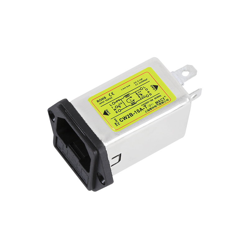
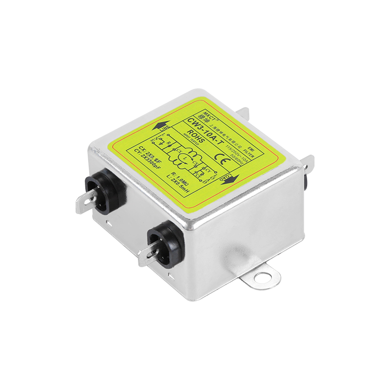
A single phase EMI filter is a passive network placed between the mains and your equipment that attenuates conducted interference travelling in both directions — noise your load injects back onto the supply, and noise arriving from the supply. The EMI filter range published for this portfolio covers single-phase and three-phase units from 1A to 40A. Selecting one comes down to four published parameters plus one installation decision: maximum continuous operating voltage, rated current, connection type, and the high-potential test voltage the datasheet quotes, matched against the environment the filter will sit in. The compliance question is separate and larger. A filter is a component; the mark that matters is applied to your finished product, and the filter is one part of the evidence you assemble.
Key Takeaways
A filter works in both directions. It limits emissions from your equipment and improves immunity to interference arriving from the supply.
Rated current is a thermal figure. Published ratings are quoted at a defined ambient, commonly 40 °C, and the filter must be derated for a hotter cabinet.
The connection type decides the installation. Insert, line-wiring, terminal block, bolt and IEC-inlet variants suit different panel practices.
The high-potential test voltage is a published specification, not a mark. Compare the datasheet figure against what your assembly requires.
Single pole and bipolar variants differ in what they reference. Choose based on your earthing arrangement, not on current rating alone.
The filter is one input to compliance, not the certificate. Standards apply to the end equipment, and the supplier's own declaration belongs in your project file.
What a Single Phase EMI Filter Actually Does
Where does the interference come from?
In a switching power supply the fastest transitions are the ones that generate the widest spectrum. Rectifier recovery, switching edges and parasitic capacitance all produce currents that would otherwise travel back along the mains conductors. A filter presents a low-impedance path that diverts those currents before they leave the enclosure, and it works symmetrically: the same network attenuates interference arriving from outside.
Which path does the filter protect — differential or common mode?
Both, and they are physically different. Differential-mode noise flows out on the live conductor and returns on the neutral, so it is attenuated by the series inductors and the line-to-line capacitor. Common-mode noise flows out on both conductors and returns through earth, so it is attenuated by the common-mode choke and the line-to-ground capacitors. This matters when you read a datasheet: a variant described as bipolar or two-stage is adding elements aimed at one of those paths, which is why two filters with identical current ratings can behave differently in the same installation.
Reading a Single Phase EMI Filter Datasheet
What do the voltage and current ratings fix?
The maximum continuous operating voltage fixes the supply you may connect, and the rated current fixes the thermal envelope. The line-type CW1B EMI filter publishes a maximum continuous operating voltage of 115/250 VAC, an operating frequency of 50/60 Hz, and a rated current range of 1A, 3A, 6A and 10A at 40 °C maximum, with up to 15A available as a customization. The phrase "at 40 °C maximum" is the part people skip. In a sealed cabinet running hotter than 40 °C, the usable current is lower than the nameplate figure, and the derating follows the same logic that applies to the power supply beside it.
Why does the high-potential test voltage matter?
It tells you what insulation level the filter is built and tested to, which is an input to the assembly's own safety assessment. The same CW1B datasheet quotes a one-minute high-potential test voltage of 1500 VDC line-to-line and 1500 VAC line-to-ground, an operating and storage temperature range of −25 °C to +85 °C classified as 25/085/21, and a line terminal wiring connection type. Read those figures as published specifications of the component, and confirm how they align with the requirements your end product must satisfy.
How does connection type change the installation?
It decides how the filter mechanically joins the panel and how much wiring discipline is needed around it. Insert-type units use quick-connect or plug-in terminations, line-type units are wired directly, and terminal-block or bolt-connection units accept field wiring with a defined torque and routing. Mixed practices in one panel are the usual source of a filter that measures correctly on the bench and misbehaves in the cabinet, because the wiring loop a technician leaves between the filter and the load can couple straight past the filter.
Table 1: Connection and mounting variants
Connection type
Published variant examples
Practical fit
Insert type
CW3-3A-T through CW3-30A-T, single pole and bipolar
CW4-3A-S through CW4-40A-S; bipolar CW4L2 and CW4E variants
High-current and vibration-prone mounts
IEC inlet
CW1D-1A-T through CW1D-10A-T; CW2B variants with switch and fuse
Bench equipment and instruments
Matching the Filter to the Installation
Panel mount or IEC inlet?
An IEC-inlet filter integrates the appliance inlet with the filter network, an approach published in the IEC-inlet filter with integrated fuse and switch family, which offers IEC socket input models from 1A to 10A with options for a switch with or without a light, a single fuse, or a double fuse. That is the right answer for equipment where the inlet is exposed and a separate filter would need its own enclosure. For a machine panel, a terminal-block or bolt-connection filter mounted close to the point where the mains enters is the conventional choice, while an insert-type filter with quick-connect terminals suits equipment assembled on a bench, where the published 1A to 15A range at 40 °C maximum covers most instrument loads.
Single pole or bipolar?
Single pole refers to the number of poles the filter network is built around; bipolar variants add elements aimed at the second reference path. The distinction matters most where the earthing arrangement is unusual or where measured common-mode noise remains high after a single-stage filter has been fitted. Both are published as standard variants across the CW3 and CW4 families, so the decision is made from measurement rather than from a specification table.
Single phase or three phase?
Single phase covers the majority of industrial control and instrumentation equipment, while three-phase three-wire versions such as the CW12B-10A-R through CW12B-40A-R exist for 380 VAC supplies. The insert-type single-phase EMI filters cover the 3A to 30A band in both single pole and bipolar configurations, which is where most automation cabinets sit. Choosing three-phase when the load is single phase adds cost and can make the earth path harder to control, so match the filter to the supply the equipment actually uses.
Table 2: Model families and current ratings
Family and variant
Published current range
Published supply
Termination
CW1B line type
1A, 3A, 6A, 10A at 40 °C
115/250 VAC, 50/60 Hz
Line terminal wiring
CW1B insert type
1A, 3A, 6A, 10A, 15A at 40 °C
115/250 VAC, 50/60 Hz
Insert quick-connect
CW3 / CW4 insert type
3A to 30A
250 VAC
Insert
CW4 terminal block
10A, 20A, 30A
220 V
Terminal block, optional guide rail
CW4 / CW4E bolt connection
3A to 40A
220 V / 250 VAC
Bolted
CW12B three-phase
10A, 20A, 30A, 40A
380 V three-phase three-wire
Terminal block
CW1D / CW2B IEC inlet
1A to 10A
IEC socket input
Inlet with optional switch and fuse
Ratings above are quoted from published model tables. Confirm the exact variant, ambient rating and termination on the datasheet before ordering.
Compliance: What CE Marking Requires of the Equipment Builder
Which standards apply, and to what?
The standards follow your product, not the filter. The EMC Directive is satisfied by meeting the applicable harmonised standards, which for industrial environments are typically the generic immunity and emission standards, while equipment in other categories follows the standards specific to that category. On the safety side, the standard governing your end product — for example IEC/EN 62368-1 for information and communication technology equipment — sets the insulation and spacing requirements your assembly must meet. EMI filters as components are covered by their own component standard, IEC 60939, which is a useful reference when reading a filter datasheet. Confirm the applicable editions and scopes with your compliance partner.
Why does the filter alone not deliver compliance?
Because emissions and immunity are properties of the finished assembly. Cable routing, earth bonding, the quality of the enclosure, the switching frequency of the supply and the length of unfiltered mains wiring inside the cabinet all influence the measurement. A correctly rated filter installed with a long untwisted loop between filter and load can perform worse than a smaller filter mounted directly at the entry point. Treat the filter as one controlled variable among several.
What documentation should be collected?
Collect the supplier's own declaration for the filter, the datasheet page carrying the rated voltage, current and high-potential test figures, and a record of the variant actually ordered. If a quick-connect or insert-type filter is used, record the mating connector part as well, because substitution changes the contact resistance and can invalidate a noise measurement taken on the prototype. Keep all of it with the project file rather than in a folder belonging to an individual engineer.
Table 3: What the filter does and does not cover
Question
Covered by the filter
Covered by the assembly
Differential-mode noise on the mains
Yes
Routing and layout influence the result
Common-mode noise to earth
Yes
Earth bonding and enclosure design
Insulation and spacing requirements
Partly, through the published test voltage
Yes, at assembly level
Emissions and immunity of the finished product
Contributes
Yes, verified by test
The mark applied to your product
No
Yes, you hold it
Illustrative method only; not a SMUN product specification.
Selection Workflow Before You Request a Quotation
Step 1 — Confirm the supply and frequency. Establish the maximum continuous operating voltage and the line frequency the equipment actually uses.
Step 2 — Derate the rated current. Start from the nameplate current, then reduce it for the real internal ambient above 40 °C.
Step 3 — Identify the interference mode. Use measurement to establish whether differential or common-mode interference dominates, and whether a single pole or bipolar variant is indicated.
Step 4 — Match the termination to your panel practice. Insert, line wiring, terminal block, bolt or IEC inlet.
Step 5 — Compare the published test voltage. Set the high-potential figure the datasheet quotes against the requirement your assembly must satisfy.
Step 6 — Fix the mounting position. As close to the mains entry as the layout allows, with the shortest practicable unfiltered loop.
Conclusion
A single phase EMI filter is a component chosen from four published figures — maximum continuous operating voltage, rated current at its stated ambient, termination type and high-potential test voltage — and then judged by how well it is installed. The installation matters as much as the choice, because the loop between the filter and the load is where most of the performance that the datasheet promises is lost.
The compliance question sits one level above the component. The mark belongs to your finished product, the standards that govern it follow its category rather than the filter's, and the filter contributes evidence rather than the conclusion. Treating a filter datasheet as a compliance document is the most common misunderstanding in this part of a design.
Before requesting a quotation, confirm the supply voltage and frequency, the derated current at your internal ambient, the interference mode your measurements show, the termination your panel practice expects, and the assembly requirement your end product must satisfy.
FAQ
Q: How do I choose between single pole and bipolar variants?
A: Base it on measurement rather than on the specification table. Single pole covers the common case; a bipolar variant adds elements aimed at the second reference path and is worth considering where measured common-mode interference remains high after a single-stage filter, or where the earthing arrangement is unusual.
Q: Does the rated current apply at any ambient temperature?
A: No. Published ratings are quoted at a defined ambient — commonly 40 °C maximum for the CW1B family — and the usable current falls as the internal temperature rises. In a sealed cabinet, derate the filter for the ambient you measured at the mounting position, exactly as you would the power supply beside it.
Q: Can I fit one filter for several loads?
A: It is possible where the loads share a supply point, but the filter then sees the combined current and the combined interference, and the unfiltered wiring inside the cabinet grows longer. Fitting the filter at the point where mains enters the enclosure, close to the dominant noise source, usually gives a better result than a larger filter serving everything.
Q: What does the high-potential test voltage tell me?
A: It describes the insulation level the filter is built and tested to, quoted as a one-minute test at a stated voltage between defined terminals. Compare the published figures against what your assembly's own safety assessment requires, and treat this as one input rather than as evidence that the finished product complies.
Q: Do I need a filter if my power supply already has one inside?
A: A supply with an internal filter reduces the interference at its own terminals, but the mains wiring inside your cabinet still carries whatever remains and can couple to nearby conductors. Whether an additional filter is required is decided by measuring the finished assembly, not by assuming the internal one is sufficient.