Read the derating curve before the headline wattage. The usable output at your cabinet ambient is usually well below the nameplate rating.
Efficiency must be read at your load, not at full load. A module that peaks at rated current can waste far more heat at 20%.
Cooling basis changes the whole number. A curve drawn at 20 LFM does not apply inside a sealed IP67 box.
Ripple is meaningless without its bandwidth. Confirm the 20MHz measurement condition and whether external capacitors are needed.
Isolation voltage and isolation capacitance are two different limits. The first blocks surges, the second lets common-mode noise through.
EMC and MTBF claims need their test conditions. Ask for the report, the model revision and the temperature behind the figure.
Introduction
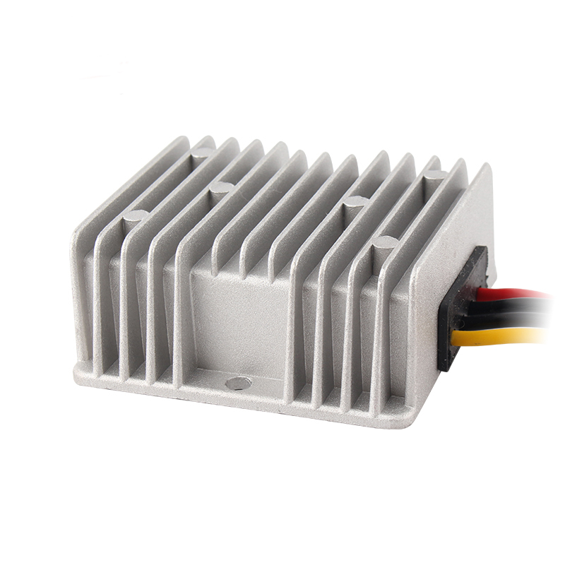
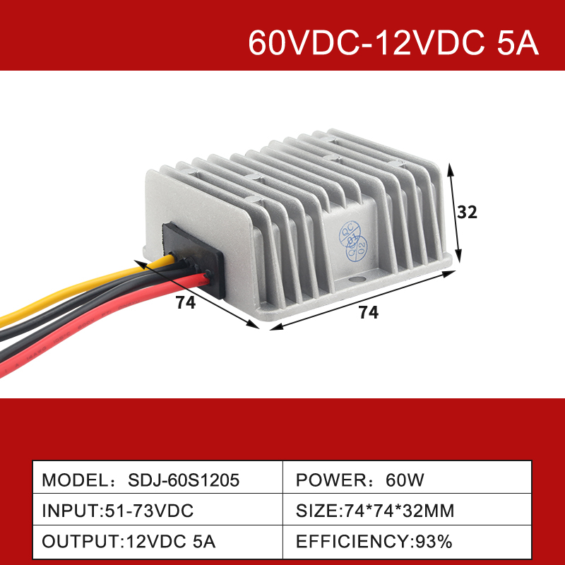
Procuring a dc dc converter module for mass production requires rigorous engineering scrutiny beyond simply matching input and output voltages. A datasheet is a legally binding engineering document that dictates how the power supply will perform under extreme operational stress. Misinterpreting these specifications can lead to catastrophic system failures, thermal runaway, and costly product recalls. Before placing a bulk order for industrial or commercial deployment, engineers must meticulously verify the thermal profiles, electrical tolerances, and compliance standards buried within the technical documentation. A 72V to 12V step-down module rated 5A to 60A is a useful reference point for how much of that detail hides in footnotes.
How to Read Efficiency and Thermal Derating Curves
When analyzing a single output dc dc converter, the relationship between efficiency, ambient temperature, and load capacity dictates the physical thermal management strategy required.
Decoding Efficiency Curves
Efficiency is the ratio of output power to input power, and the lost energy dissipates as heat. Datasheets provide efficiency curves plotted against load current (typically 10% to 100%) and various input voltages (minimum, nominal, and maximum). It is crucial to evaluate the efficiency at your system's typical operating load, not just the peak "marketing" number. A converter that boasts 92% efficiency at full load might drop to a thermally dangerous 75% at a 20% light load.
Understanding the Thermal Derating Graph
The thermal derating curve is arguably the most critical graph in the datasheet. It illustrates the maximum allowable output power as ambient temperature increases. For instance, a 50W module might provide full power up to 55°C, after which the output capacity steeply linearly derates to 0W at 85°C. Engineers must map their enclosure's internal ambient temperature to this curve to ensure the module will not enter thermal shutdown during summer months or heavy operational cycles.
Natural Convection vs. Forced Air Cooling
Pay close attention to the conditions under which the derating curve was generated. Most baseline curves assume free-air natural convection (e.g., 20 LFM). If your application operates in a sealed IP67 enclosure with zero airflow, you must apply a much harsher derating factor. Conversely, datasheets often provide secondary curves showing improved power delivery if forced air (e.g., a cooling fan providing 200 LFM) is utilized.
Table 1: Efficiency and Derating Checks on a Module Datasheet
Checkpoint
What the datasheet states
What to confirm before ordering
Efficiency at 20% load
A second curve or table row
Value at your standby current, not the peak
Full-load ambient ceiling
Temperature where derating starts
Your cabinet internal ambient at the hottest hour
Cooling basis
Free air (e.g. 20 LFM) or forced air (200 LFM)
Same airflow as the installed enclosure
Derating slope
Power against ambient, down to zero
Margin left at the top of your ambient range
Thermal path
Case, baseplate or potted body
How heat leaves the module in your mounting
Ripple, Noise, and Isolation Specifications Explained
For systems requiring clean power, such as a dc dc converter module 12v feeding sensitive analog sensors or communication arrays, understanding electrical noise parameters is vital.
Ripple and Noise (Vp-p)
Ripple refers to the inherent low-frequency AC voltage superimposed on the DC output, tied to the switching frequency of the converter. Noise comprises high-frequency voltage spikes generated by the rapid switching transitions of the internal MOSFETs. This combined metric is usually expressed in millivolts peak-to-peak (mVp-p), measured with a 20MHz bandwidth oscilloscope. For critical analog-to-digital converters, ensuring this value remains below 50mVp-p is often necessary. Datasheets will specify if external capacitors (e.g., a 10µF tantalum and a 0.1µF ceramic) are required to achieve the stated noise levels.
Transient Response Time
When a load suddenly changes—for example, a motor turning on or a processor waking from sleep—the output voltage will temporarily dip or spike. The transient response specification details the maximum voltage deviation (usually as a percentage) and the recovery time (in microseconds) required for the output to return to its regulated tolerance band. Faster recovery times are essential for preventing logic errors in digital circuits.
Isolation Voltage and Capacitance
Isolation voltage (e.g., 1500VDC or 3000VDC) dictates the dielectric strength between the input and output terminals. Equally important, but often overlooked, is the isolation capacitance. A high isolation capacitance allows high-frequency common-mode noise to bridge the isolation barrier. For medical or ultra-low noise applications, an isolation capacitance below 100pF is highly desirable to maintain strict signal integrity.
Table 2: Ripple, Noise and Isolation Figures and Their Consequences
Validating a dc dc converter specification involves ensuring the module complies with international standards for reliability and electromagnetic compatibility.
Electromagnetic Compatibility (EMC)
A converter acts as both a victim and a source of electromagnetic interference (EMI). The datasheet must indicate compliance with standards such as EN55032 for radiated and conducted emissions. Crucially, check the fine print: does the module meet these standards standalone, or does it require an extensive external EMI filter circuit? Failing to account for external filter components can derail PCB space allocation and project budgets.
Mean Time Between Failures (MTBF)
MTBF is a statistical prediction of reliability, usually calculated using standards like MIL-HDBK-217F or Telcordia SR-332. It is expressed in hundreds of thousands or millions of hours. However, MTBF is highly temperature-dependent. A module boasting 1,000,000 hours MTBF at 25°C may drop to 200,000 hours at 65°C. Always verify the temperature at which the MTBF was calculated to gauge true long-term reliability.
Built-in Protection Mechanisms
Industrial environments are unpredictable. Ensure the datasheet explicitly lists continuous short-circuit protection (SCP) with automatic recovery, over-voltage protection (OVP) to clamp dangerous output spikes, and under-voltage lockout (UVLO) to prevent erratic behavior when the input battery is deeply discharged. Furthermore, over-temperature protection (OTP) is a critical fail-safe that shuts down the module before permanent silicon damage occurs.
A 48V to 24V unit rated 3A to 85A is a practical example to test the checklist against, because the protection and isolation rows sit on the same page as the derating curve.
Conclusion
Carefully deciphering a dc dc converter module datasheet is the only way to ensure power system reliability and prevent costly field failures. By systematically verifying thermal derating limits, analyzing ripple and noise parameters, and confirming EMC and MTBF compliance, engineers can confidently approve components for high-volume manufacturing.
The next step is to run the same checks on a sample from the production lot rather than on the qualification sample alone: measure ripple at the stated bandwidth, confirm the derating curve against the real enclosure ambient, and ask for the EMC report that carries the model number and revision you are buying.
Need power modules backed by comprehensive specifications and robust industrial performance? Explore our DC-DC Converter Modules to find the right technical fit for your next demanding application, or narrow the shortlist through the isolated DC-DC converter range where the load needs a barrier.
FAQ
Q: Which specification on a DC-DC converter datasheet matters most?
A: The thermal derating curve, because it decides the current you can actually draw at your enclosure ambient. Voltage and current headlines are easy to compare; the derating graph is where two otherwise similar modules separate in the field. Ask for it drawn under your cooling condition.
Q: How do I read a thermal derating graph correctly?
A: Find the ambient temperature inside your enclosure, read across to the curve, then down to the permitted output. Repeat for the worst case in summer. If the curve was drawn at 20 LFM and your box is sealed, apply a harsher factor or request a curve taken under your conditions.
Q: What ripple and noise figure should I ask a supplier for?
A: Ask for mVp-p at a stated bandwidth, normally 20MHz, together with the input voltage and load at which it was measured. Then ask whether external capacitors are needed to reach that figure, since the quoted number often assumes them. Without both conditions the figure cannot be reproduced.
Q: Does a 1500VDC isolation rating make a module safe across mains?
A: No. The rating describes dielectric strength for a stated test duration, not a safety category. The supplier should provide the test report, and the buyer should confirm that creepage, clearance and the end-product standard are met for the intended application.
Q: Why does MTBF fall when the temperature rises?
A: MTBF is calculated from component failure rates that rise with junction temperature, so the same design scores lower at 65°C than at 25°C. Always compare figures calculated at the same temperature and standard, such as MIL-HDBK-217F or Telcordia SR-332. A figure quoted without its reference temperature is not comparable.