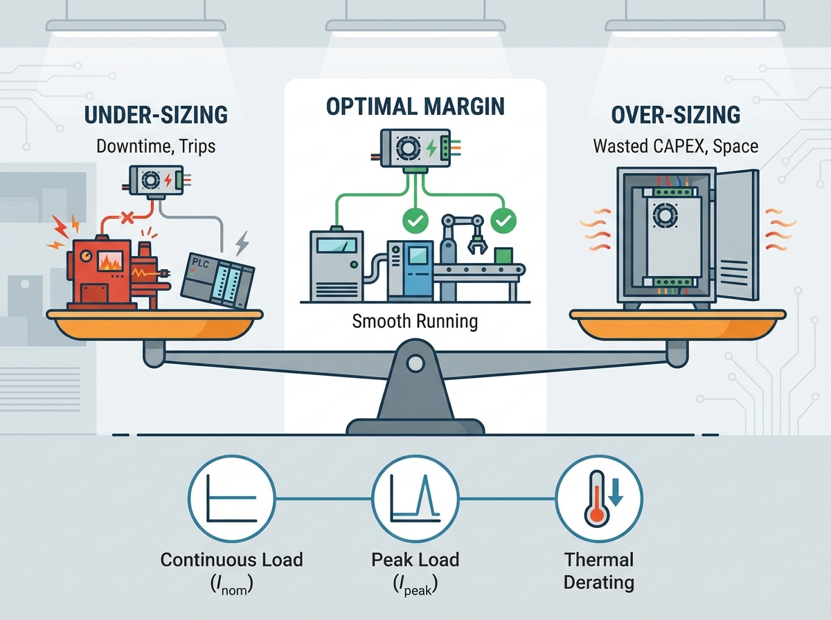
Industrial automation systems thrive on consistent and reliable power delivery. Yet, a single voltage dip from an inadequate unit can bring entire production lines to a sudden, grinding halt. Under-sizing your equipment inevitably leads to erratic programmable logic controller (PLC) behavior. It also causes nuisance tripping and costly, unplanned downtime. Conversely, aggressively over-sizing units wastes valuable cabinet space. It drives up initial capital expenditure (CAPEX) unnecessarily.
Calculating an accurate power supply current margin bridges the critical gap between theoretical electrical loads and harsh real-world operating conditions. It ensures system reliability without unnecessary component bloat. In this guide, you will learn a concrete calculation framework for handling dynamic peaks. We will also explore essential temperature derating rules and specific vendor evaluation criteria. These steps will help you finalize your power specifications confidently and keep your industrial processes running smoothly.
Key Takeaways
A standard continuous power supply current margin is typically 20% to 30% above the maximum steady-state load, but dynamic loads require distinct peak calculations.
Peak current durations (e.g., 3 seconds vs. 30 milliseconds) strictly dictate whether you need a larger continuous supply or a unit with a specific "power boost" feature.
Thermal derating environments heavily influence margin calculation; a 10A supply may only deliver 7.5A at 60°C.
Form factor selection—particularly choosing between an Enclosed Power Supply and a DIN Rail Power Supply—fundamentally alters thermal dissipation and required safety margins.
The Business Case: Balancing Reliability vs. Over-Specification
Engineering teams frequently struggle to find the optimal middle ground during power specification. You must balance the physical safety of your equipment against strict procurement budgets. Striking this balance requires a deep understanding of how electrical loads behave over time.
The Cost of Under-Sizing
When you select a unit based purely on nominal load, you invite severe operational risks. Nuisance tripping is the most common symptom of under-sizing. This occurs when transient spikes trigger the unit's internal short-circuit protection. It forces the system to shut down unexpectedly. Accelerated component aging presents another hidden danger. Running a unit continuously at its maximum limit generates excessive internal heat. This heat degrades electrolytic capacitors rapidly. The Arrhenius equation states that capacitor lifespan roughly halves for every 10°C increase in operating temperature. Furthermore, under-sized units often cause unpredictable system reboots during motor startup. These restarts corrupt data and ruin active production batches.
The Trap of Over-Sizing
To avoid under-sizing, some engineers apply arbitrary 100% safety margins. They double the calculated load and purchase massive units. This approach creates distinct problems. First, it severely increases the physical footprint inside the control cabinet. Panel space is extremely expensive. Second, it reduces electrical efficiency. Switch-mode power devices operate most efficiently between 50% and 80% of their rated load. Operating a massive unit at only 20% capacity generates unnecessary heat waste. Finally, over-sizing inflates procurement costs unnecessarily. You pay for internal silicon and copper you will never utilize.
Success Criteria
A finalized specification must accomplish four distinct goals. It must cover the steady-state draw comfortably. It must accommodate known transient spikes without dropping voltage. It must account for environmental thermal derating inside closed panels. Finally, it must optimize the overall price-to-performance ratio for your specific application.
Step-by-Step Calculation for Peak Current Margin
You cannot guess your way to a reliable system. A methodical approach ensures your specification matches reality. Follow this four-step engineering framework to determine your exact requirements.
Step 1: Audit Total Continuous Load ($I_{nom}$)
Start by summing the nominal current draw of all active components. You must calculate the load when devices operate simultaneously under standard conditions. Include sensors, PLCs, human-machine interfaces (HMIs), and standard relays. Review the datasheet for every component on your bill of materials. If a device lists a power consumption range, use the maximum steady-state value. This baseline figure represents your $I_{nom}$.
Next, isolate your inductive and capacitive loads. These components demand massive inrush current when energized. Direct current (DC) motors, heavy contactors, and large solenoids represent typical inductive loads. Determine the exact duration of these peak demands. A motor might pull 150% of its rated current for three full seconds. Conversely, an LED driver might demand 300% for only 30 milliseconds. Map out the duty cycle of these events. Frequent peaks require different cooling strategies than rare, isolated events.
Step 3: Apply the Environmental Derating Factor
Heat severely restricts current delivery. You must locate the manufacturer’s specific derating curve for your chosen device. Identify the maximum expected operating temperature inside your control cabinet. Most industrial units provide 100% capacity up to 50°C. Beyond this point, they typically lose 2% to 2.5% capacity per degree Celsius. Calculate the actual capacity loss at your maximum temperature. We call this the thermal derating deficit.
Step 4: The Final Margin Formula
Now, combine your data into a concrete calculation. Apply the following rules to establish your baseline and verify your peaks.
Peak verification: Compare your calculated $I_{peak}$ against the unit's specified peak capability. Ensure the selected unit's certified peak duration exceeds your system's longest transient event.
If your baseline calculation suggests a 10A unit, but your 3-second motor startup hits 20A, you face a choice. You must either buy a 20A continuous unit or find a 10A unit featuring a specialized 200% power boost function.
Navigating Dynamic Loads and Inrush Current Risks
Dynamic loads deceive many engineers. A system might look perfectly safe on paper but fail repeatedly in the field. Understanding load behavior helps you avoid standard specification pitfalls.
Motor and Solenoid Startups
Inductive loads fight changes in current flow. When you apply voltage to a stationary motor, it lacks back-electromotive force (EMF). As a result, it can draw three to five times its nominal current for several milliseconds or seconds. Standard power devices lack the internal capacitance to support this massive draw. They view the sudden demand as a fault. They trigger short-circuit protection and enter "hiccup mode". This mode shuts the output down and restarts it repeatedly. If your margin calculation ignores this behavior, your motors will simply twitch instead of starting.
Capacitive Loads
Capacitive loads present a different challenge. Empty capacitors act like short circuits the moment you apply power. LED drivers and complex network switches contain massive input capacitor banks. They cause incredibly steep, instantaneous current spikes. While inductive spikes might last seconds, capacitive spikes often resolve in microseconds. However, the amplitude is severe. If the spike drops the system voltage below the PLC's minimum operating threshold, the controller will reboot instantly.
Implementation Reality
You should not massively increase your continuous current rating just to handle short, infrequent spikes. Doing so violates our rule against over-sizing. Instead, evaluate units engineered specifically for dynamic loads. Look for devices offering "Peak Power" or "Power Boost" capabilities. These advanced units can sustain 150% to 200% of their rated current for 3 to 5 seconds. They handle the motor start smoothly. Afterward, they settle back into their highly efficient continuous rating.
Dynamic Load Characteristics Chart
Load Type
Common Examples
Inrush Amplitude
Typical Duration
Protection Risk
Inductive
DC Motors, Solenoids, Contactors
3x to 5x nominal
100ms to 5 seconds
Triggers Hiccup Mode
Capacitive
LED Drivers, Network Switches
Up to 10x nominal
1ms to 30ms
Causes Voltage Dips
Resistive
Heaters, Incandescent Bulbs
1x to 1.5x nominal
Instantaneous
Minimal Risk
Form Factor Evaluation: Thermal Constraints and Mounting
Your margin calculation relies heavily on how well the unit sheds heat. Form factor fundamentally alters thermal dissipation. You must align your safety margins with your physical mounting strategy.
DIN Rail Power Supply Margins
A DIN Rail Power Supply mounts directly onto a standardized metal rail inside a control cabinet. You typically find them in high-density automation panels. This form factor relies almost exclusively on natural convection cooling. Cold air enters the bottom vents, absorbs heat, and exits the top vents.
When calculating margins for this form factor, vertical clearance rules are absolute. Manufacturers mandate specific clearance gaps above and below the unit. If you block these vents with thick wire ducts, the internal temperature skyrockets. Adjacent heat-generating devices also disrupt cooling. If you mount a hot variable frequency drive (VFD) directly beside the supply, you must increase your thermal derating deficit significantly. If forced airflow (cabinet fans) is unavailable, your continuous current margin must often be higher to compensate for stagnant heat.
Enclosed Power Supply Margins
An Enclosed Power Supply features a protective metal casing. You typically mount these units via chassis screws. You will find them in standalone machinery, harsh factory floors, or high-vibration environments where DIN rails might fail. They often utilize baseplate cooling or built-in mechanical cooling fans.
Enclosed units generally handle higher ambient temperatures more gracefully. Baseplate cooling transfers heat directly into the machine's heavy metal frame. However, units relying on internal fans introduce mechanical risk. Mechanical fans eventually fail due to dust ingress or bearing wear. When sizing an enclosed unit with a fan, evaluate the Mean Time Between Failures (MTBF) at your calculated current load. If the fan dies, the unit will drastically derate its output or shut down entirely. To mitigate this risk, many engineers specify enclosed units large enough to operate passively even if the fan fails.
Form Factor Comparison
Feature
DIN Rail Units
Enclosed Chassis Units
Cooling Mechanism
Natural convection (chimney effect)
Fan-forced or baseplate conduction
Space Efficiency
High density, vertical orientation
Larger footprint, horizontal mounting
Vibration Tolerance
Moderate (rail clips can detach)
Excellent (secure screw mounting)
Derating Sensitivity
Highly sensitive to clearance gaps
Sensitive to ambient dust/fan failure
Vendor Evaluation: Reading Spec Sheets with Engineering Skepticism
Datasheets often obscure critical limitations behind marketing terminology. You must approach vendor specifications with healthy engineering skepticism. A calculated margin holds no value if the hardware fails to perform as advertised.
Continuous vs. Peak Ratings
Never conflate short-term peak ratings with continuous operating capacity. Some manufacturers label a unit as "240W" in large font. However, reading the fine print reveals it only sustains 240W for three seconds. Its actual continuous rating might only be 120W. Reject manufacturers that hide these distinctions. Always demand independent verification. Look for UL, TUV, or CE certifications confirming the steady-state thermal testing results.
Overload Protection Behavior
You must evaluate exactly how the unit behaves when your load breaches the calculated margin. Devices generally utilize one of two protection topologies.
"Constant Current Limitation" is ideal for starting heavy industrial loads. When the load demands excessive current, the unit caps the current at its maximum limit. It then drops the voltage proportionally. This allows heavy motors to spool up gradually without crashing the system.
Conversely, "Foldback" or "Hiccup mode" shuts the output down entirely upon sensing an overload. The unit waits a few seconds and tries again. While excellent for clearing actual short circuits, hiccup mode may fail entirely to start inductive loads. Ensure you select Constant Current Limitation if your system features large motors.
Shortlisting Logic
Use a strict, repeatable process to filter your vendor options. Follow these sequential steps:
Filter by nominal output: Take your $I_{nom}$ calculation and add your 25% buffer. Discard any units falling below this continuous rating.
Filter by peak duration: Match your measured transient spike durations against the manufacturer’s certified power boost window.
Verify the thermal curve: Cross-reference the derating curve at your intended cabinet temperature. Ensure the unit still meets step 1 requirements at 60°C.
Select for longevity: Compare total lifecycle cost, warranty periods, and established MTBF metrics across your remaining choices.
Conclusion
Calculating the correct margin remains an exercise in precise data collection, not arbitrary guesswork. Identifying your steady-state loads establishes your baseline. Mapping transient spikes allows you to navigate inductive startup risks successfully. Applying accurate temperature derating ensures the unit survives harsh environments. By following this systematic framework, you protect your system integrity without inflating initial capital costs.
Take immediate action on your next build. Review your current bill of materials thoroughly. Isolate your highest inductive loads and measure their exact peak durations. Finally, always consult your supplier’s thermal derating curves before you issue the final Purchase Order.
FAQ
Q: What is a safe rule of thumb for power supply current margin?
A: A 20% to 30% margin above your maximum continuous load serves as the industry standard for stable environments. However, this general rule is easily superseded. Specific thermal derating requirements or exceptionally high inrush loads demand custom calculations to ensure safety.
Q: Can I use a higher current power supply than required?
A: Yes. A device will only draw the exact current it needs to operate. However, significantly over-sizing a unit (e.g., >50%) reduces its electrical efficiency. It also increases the physical footprint inside your cabinet and raises your upfront hardware costs unnecessarily.
Q: How does temperature affect my current margin calculation?
A: Most industrial power devices begin to "derate" or lose capacity above 50°C to 60°C. If your internal cabinet temperature reaches 60°C, a unit might only provide 75% of its rated continuous current. Your baseline margin must be increased to compensate for this thermal deficit.
Q: What happens if the peak current exceeds the power supply rating?
A: Depending on the specific internal topology, the output voltage will drop dramatically. Alternatively, the unit may enter "hiccup mode," which means it shuts down and restarts continuously. This behavior immediately resets connected controllers and causes extensive operational downtime.