Galvanic isolation breaks ground loops. A transformer barrier stops DC and low-frequency current from passing between input and output, which removes circulating currents in multi-point grounded systems.
1500VDC covers most industrial work. 3000VDC and above is reserved for medical, traction and high-transient environments where surge energy can reach the secondary side.
Creepage and clearance set the real limit. The isolation figure on a datasheet is only valid if the physical spacing along the surface and through the air supports it.
Topology follows power level. Flyback serves sub-50W auxiliary rails, forward covers 50–200W, and push-pull takes over above 200W where efficiency and duty cycle matter.
Four parameters decide whether a module survives. Input range, thermal derating, output ripple and protection behaviour separate a specification that works from one that fails in the field.
Isolation is not a warranty against EMC. An isolated module still needs filtering if it feeds conducted-emission-sensitive equipment.
Introduction
An isolated dc dc converter is a critical component in industrial power systems, designed to transfer electrical power between two circuits while maintaining a galvanic barrier. This isolation prevents the flow of direct current between the input and output, protecting sensitive downstream components from transient voltage spikes, ground loops, and electrical noise. By utilizing a high-frequency transformer, these converters ensure safety and system reliability in harsh operational environments, ranging from telecommunications infrastructure to heavy machinery control panels. Understanding the nuances of isolation ratings, internal topologies, and essential technical specifications is fundamental for engineers tasked with designing robust power distribution networks.
What is Isolation Rating? (Creepage and Clearance Explained)
When evaluating an isolated dc to dc converter, the isolation rating is the primary specification determining the level of protection provided. This rating signifies the maximum voltage the galvanic barrier can withstand for a specified duration without breaking down.
1500V vs. 3000V Isolation Levels
Standard industrial converters typically offer a 1500VDC isolation rating, which is sufficient for breaking ground loops and preventing standard electrical noise interference in conventional logic circuits. However, in environments with higher transient risks, such as medical equipment or heavy industrial motor drives, a 3000VDC or even higher isolation level is mandatory. The higher rating guarantees that voltage surges on the input side do not cascade and permanently damage delicate microprocessors on the output side.
Understanding Creepage Distance
Creepage refers to the shortest path between two conductive parts measured along the surface of the solid insulating material. In power supply design, maintaining an adequate creepage distance prevents tracking—a phenomenon where high voltage creates a conductive carbonized path across the dielectric surface. A higher operating voltage requires a proportionally larger creepage distance to comply with international safety standards such as IEC 62368-1.
The Role of Clearance
Clearance is defined as the shortest distance between two conductive elements measured through the air. It determines the converter's ability to withstand instantaneous electrical arcs or flashovers. Properly engineered clearance ensures that high-voltage transients do not bridge the physical gap between the primary and secondary sides of the transformer, thereby maintaining the integrity of the galvanic isolation barrier.
Table 1: Isolation Rating Against Typical Application
Isolation Rating
Withstand Basis
Typical Application
Design Note
1000VDC
Basic functional separation
Low-voltage logic rails inside one enclosure
Not a safety barrier
1500VDC
Reinforced for 250VAC-class systems
Industrial control panels, 24V and 48V buses
Default choice for factory automation
3000VDC
Reinforced with higher transient margin
Medical equipment, motor drives, traction auxiliaries
Verify creepage and clearance, not just the figure
6000VDC
High-integrity barrier
High-voltage battery systems, grid-tied equipment
Requires compliance documentation
Flyback vs Forward vs Push-Pull: Which Topology to Choose?
Selecting the right internal architecture for a dc to dc isolated converter dictates its efficiency, footprint, and suitability for specific power ranges. Engineers must match the topology to the load requirements.
Flyback Topology for Low Power Applications
The flyback topology is widely utilized in sub-50W applications due to its simplicity and minimal component count. It employs a coupled inductor to store energy during the switch's on-time and release it to the secondary side during the off-time. This eliminates the need for a separate output inductor, making it highly cost-effective and compact. However, flyback converters generally exhibit higher output ripple currents, which may necessitate additional filtering for noise-sensitive loads.
Forward Topology for Medium Power
For medium power requirements, typically ranging from 50W to 200W, the forward converter topology becomes more advantageous. Unlike the flyback design, a forward converter transfers energy directly to the output while the primary switch is conducting. It utilizes a dedicated output inductor and an energy recovery winding to manage the transformer's magnetic flux. This results in lower output ripple and higher efficiency, albeit with a slightly larger PCB footprint.
Push-Pull Topology for High Efficiency
When dealing with higher power demands exceeding 200W, the push-pull topology is highly effective. It utilizes two active switches that alternately drive a center-tapped transformer, utilizing the full B-H curve of the magnetic core. This alternating action allows for maximum power transfer and highly efficient operation. Push-pull converters are excellent for stepping up low input voltages to higher output levels, frequently seen in renewable energy inverters and heavy-duty industrial applications.
Table 2: Topology Selection Matrix
Parameter
Flyback
Forward
Push-Pull
Typical power range
Under 50W
50W–200W
Above 200W
Component count
Lowest
Medium
Highest
Output ripple
Higher
Lower
Lowest
Efficiency band
Moderate
Good
Best
Transformer role
Energy storage
Direct transfer
Full B-H curve
Best fit
Auxiliary and bias rails
Control and instrumentation supplies
Traction, inverters, high-power racks
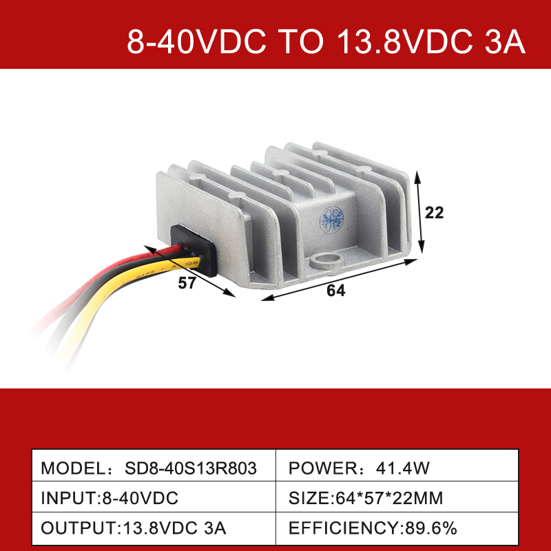
For converters that sit between these bands, the practical answer is usually a single-switch forward design with an upgraded output filter rather than a scaled-down push-pull stage. A 350W isolated DC-DC converter with multi-voltage output shows how the higher-power band is packaged for instrumentation racks, while IP68 waterproof boost-buck units rated 8–40V to 13.8V apply the same principles to sealed vehicle-mounted hardware.
Specification Checklist for Isolated Converters
Before integrating an isolated dc dc power supply into your system architecture, verifying key technical specifications against your application's operational profile is vital.
Input Voltage Range
Industrial buses are notorious for voltage fluctuations. A robust converter must feature a wide input voltage range (such as 2:1 or 4:1 ratios, e.g., 9-36VDC or 18-72VDC). This wide tolerance ensures the device operates reliably even during severe battery voltage drops or inductive load dumps on the main supply line.
Thermal Derating and Operating Temperature
Power modules generate heat, and their performance degrades as ambient temperatures rise. The thermal derating curve indicates the maximum output power permissible at a given ambient temperature without risking thermal shutdown or component degradation. High-quality converters incorporate advanced potting compounds and optimized heatsink interfaces to maintain full load operation up to 70°C or 85°C before derating begins.
Output Ripple and Noise Limits
Ripple and noise, measured in millivolts peak-to-peak (mVp-p), represent the residual AC components superimposed on the DC output. For driving analog sensors, RF transceivers, or high-speed ADCs, ultra-low ripple is non-negotiable. Reviewing the datasheet for integrated LC filtering capabilities and understanding the measurement bandwidth (typically 20MHz) is crucial for precision engineering.
Short Circuit and Over-Voltage Protection (OVP)
Continuous short circuit protection (SCP) with auto-recovery ensures that the converter can withstand a dead short on the output terminals indefinitely, automatically resuming normal operation once the fault is cleared. Similarly, OVP clamps the output voltage, preventing an internal failure from passing a destructive high voltage to the connected load.
Table 3: Specification Benchmarks Before a Bulk Order
Spec
What to Confirm
Failure Mode If Skipped
Input range
Ratio (2:1 or 4:1) and absolute minimum
Dropout during battery sag or load dump
Derating curve
Full-load ambient ceiling
Thermal shutdown inside a sealed cabinet
Output ripple
mVp-p and measurement bandwidth
ADC jitter and sensor drift
Protection
SCP auto-recovery and OVP clamp
Load destroyed by a failed pass element
Isolation
Rating plus creepage and clearance
Barrier breakdown after field transients
Conclusion
Selecting the right isolated dc dc converter starts with matching the barrier to the environment rather than to the highest number on a datasheet. A 1500VDC part is the correct answer for most control panels; 3000VDC and above earns its cost only where surge energy or patient-contact rules demand it.
The next step is to take the four parameters in Table 3 and check them against your actual operating profile — measured bus sag, cabinet internal ambient, and the ripple tolerance of whatever sits downstream. Any gap between the datasheet and the measured condition is where field failures originate.
Once those numbers reconcile, shortlist two or three modules and request samples for a bench test at the temperature extremes you expect. You can compare the full isolated DC-DC converter range or review the wider DC-DC converter catalogue before committing to a production order.
FAQ
Q: What is the difference between isolated and non-isolated DC-DC converters?
A: An isolated converter uses a transformer between input and output, so no DC path exists across the barrier; a non-isolated converter shares a common ground. Isolation removes ground loops and blocks transients from reaching the load, at the cost of efficiency, size and price.
Q: What isolation voltage do I need for a 48V industrial bus?
A: For a nominal 48V bus inside a control panel, 1500VDC is normally sufficient and is the industry default. Move to 3000VDC when the panel shares an environment with motor drives, welders or traction equipment, or when the end-product safety standard demands reinforced separation.
Q: Does a higher isolation rating reduce efficiency?
A: Slightly. A stronger barrier generally means a larger transformer, more insulation and wider spacing, all of which add winding and core losses. The penalty is usually small compared with conduction losses in the switching stage, so specify the rating the application needs rather than the highest available.
Q: Can an isolated converter be used to break a ground loop?
A: Yes, and this is one of its most common uses. Because no galvanic path crosses the transformer, circulating current between two grounded points cannot flow through the converter. This stops low-frequency hum and offset errors in measurement chains that span separate cabinets.
Q: How do I verify that a converter is genuinely isolated?
A: Check the datasheet for an isolation voltage figure, an insulation resistance value and a stated test duration, then confirm that the mechanical drawing shows adequate creepage and clearance. A step-down unit for 48V to 24V buses shows how these values appear on a real specification sheet.