Imagine stepping onto a modern factory floor. You are surrounded by heavy machinery, humming motors, and robotic arms. While this setup is a marvel of engineering, it is also a nightmare for sensitive electronics. Your power conversion systems are constantly bombarded by severe electrical noise, unpredictable voltage fluctuations, and extreme thermal stress. If you do not protect your equipment, these harsh conditions will quickly lead to system failures, unexpected downtime, and costly repairs. That is why choosing the right hardware, like a high-quality pfc enclosed power supply, becomes absolutely critical for keeping your operations running smoothly.
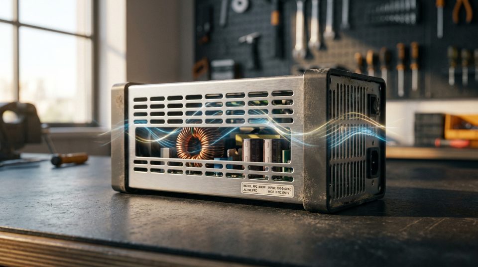
To survive in these tough conditions, your power supply needs two main lines of defense: active Power Factor Correction (PFC) and a rugged mechanical design. Active PFC acts as a critical standard by actively shaping the input current. This minimizes reactive power losses and helps you comply with strict international harmonic current regulations. At the same time, the physical structure matters just as much. When you look at options in the Enclosed Type Power Supply p category, you will find that these metal-shielded boxes do more than just block dust, metal shavings, and debris. They are specifically engineered to optimize internal heat dissipation, ensuring that sensitive components like internal capacitors do not overheat and fail prematurely.
Superior Electrical Efficiency and Wide Input Tolerance of a PFC Enclosed Power Supply
When you run industrial machinery, you need a power supply that does not flinch when the grid fluctuates. How do you ensure your system stays up and running while keeping your electricity bills under control? The answer lies in three key design features: active power factor correction, a wide input voltage range, and high conversion efficiency. Together, these features protect your sensitive components and reduce overall energy waste.
Active PFC: Shaping Your Current for Maximum Efficiency
In a standard LRS single output enclosed supply, the current is drawn from the wall in short, harsh spikes rather than a smooth wave. This mismatch between voltage and current creates "reactive power"—electricity that travels back and forth through the wires without doing any useful work. This wastes energy and heats up the power grid.
To solve this, active Power Factor Correction (PFC) circuitry acts as a smart controller. It actively shapes the incoming current so that it flows in perfect harmony with the voltage. This process brings the power factor up to a highly efficient 0.95 or greater. If you are looking for a reliable unit that showcases these features in practice, the RSP-320 320W PFC power supply provides a great example of how active correction keeps energy waste to a minimum. By using active PFC, your facility draws less total current for the same amount of actual work, helping you comply with strict utility regulations and reducing the load on your electrical wiring.
Universal Input: One Unit for the Whole World
If you build machines for a global market, stocking different power supplies for different countries is a logistical headache. A high-quality pfc enclosed power supply solves this issue by offering a universal input range of 85V to 264V AC.
This wide tolerance means the exact same power supply can run safely on:
Standard 115V AC systems in North America.
Higher 230V AC grids in Europe and Asia.
Unstable industrial grids where the voltage regularly sags or surges.
For original equipment manufacturers (OEMs), this universal compatibility simplifies inventory. You only need to test and stock a single model, knowing it will perform reliably wherever your finished machine is shipped.
High Conversion Efficiency and Capacitor Longevity
Conversion efficiency tells you how much of the AC power from the wall actually makes it to your DC-powered equipment. With an efficiency rating reaching up to 88%, only 12% of the incoming power is lost as waste heat.
Minimizing heat is critical when dealing with an enclosed chassis. Unlike open-frame designs that rely on open air to cool down, enclosed models trap heat more easily. Inside every power supply are electrolytic capacitors, which are highly sensitive to temperature. As a general rule of thumb in electronics, every 10°C drop in operating temperature can double the lifespan of these capacitors. By keeping conversion efficiency high, the power supply generates less internal heat, keeping these vital capacitors cool and extending the overall lifespan of your equipment.
To help you decide between an enclosed model and an open-frame alternative for your next integration project, consider these practical differences:
Feature
Enclosed PFC Power Supply
Open-Frame Power Supply
Physical Protection
High; the metal casing blocks dust, dirt, and accidental contact.
Low; exposed circuitry requires an external protective box.
Thermal Control
Relies on conduction cooling through the metal frame or built-in fans.
Relies heavily on the overall system's airflow to stay cool.
OEM Integration
Easy drop-in mounting with standardized mounting holes.
Requires careful planning for safety clearances and insulation.
By choosing an enclosed unit with active PFC, you get a rugged, highly efficient solution that is ready to handle the unpredictable nature of industrial power grids.
Key Takeaways
Active PFC circuitry actively shapes the input current to achieve a power factor greater than 0.95, significantly reducing energy waste in industrial grids.
Universal input capability supports a wide range of 85~264V AC, allowing the same power supply unit to operate globally across different grid standards.
High-efficiency design reaching up to 88% minimizes internal heat generation, extending the operational lifespan of internal electrolytic capacitors.
Advanced Power Resilience and Transient Protection
Have you ever wondered how industrial equipment survives when the electrical grid goes haywire? In busy factories, heavy machinery turns on and off constantly, sending violent electrical shocks and voltage spikes through the power lines. If your power supply is weak, these spikes will fry its internal parts and ruin the expensive equipment connected to it. To prevent these disasters, a rugged power supply needs advanced safeguards to absorb sudden shocks and keep your system running smoothly.
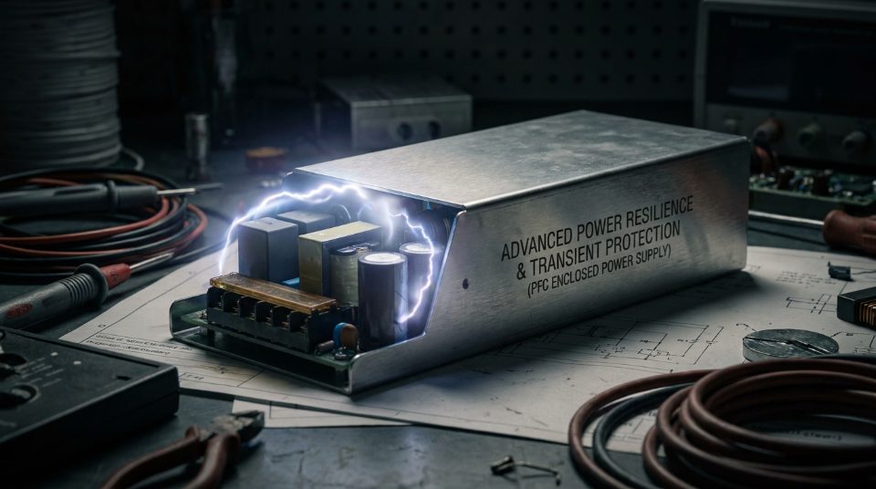
One of the most critical safeguards is heavy-duty input protection. In unstable grids, the input voltage can suddenly shoot up far beyond normal levels. High-quality units are designed to withstand a punishing 300V AC surge input for up to 5 seconds. Instead of failing immediately or letting the high voltage pass through to your sensitive controllers, the power supply acts as a protective shield. It absorbs this temporary swell, keeping downstream components completely safe from damage. This level of ruggedness is a hallmark of industrial-grade designs, such as the LRS series thin enclosed power supply, which are built to endure harsh grid environments where cheaper consumer units would fail instantly.
Besides protecting against incoming spikes, your power supply also has to handle the sudden demands of your own equipment. When you start an inductive motor, a pump, or a large bank of capacitors, they require a massive burst of energy just to get moving. This initial surge is called startup current, and it can easily be double or triple the normal running current.
If your power supply only provides its rated continuous power, this sudden demand will trigger its safety shutdown, causing your system to stall. To solve this, a high-performance pfc enclosed power supply offers a 200% peak power capability. This feature allows the unit to deliver twice its rated power for a few brief moments during startup.
Here is how this peak power overhead benefits your system:
No Need to Oversize: You do not have to buy a massive, expensive 600W power supply just to handle a 300W motor's brief startup surge.
System Stability: The voltage remains stable during high-demand moments, preventing your control computers from resetting.
Long-Term Reliability: The components are built to handle these quick thermal and electrical stresses without degrading over time.
By combining 300V AC surge tolerance with a generous 200% peak power buffer, these power units ensure your machinery starts reliably and stays protected against the wildest grid fluctuations.
Key Takeaways
Heavy-duty input protection allows the unit to safely withstand 300V AC surge inputs for up to 5 seconds without damaging downstream components.
A 200% peak power capability provides the necessary overhead to handle short-term surge loads during inductive motor or capacitive startups.
Thermal Endurance and Flexible Design Architectures
While having strong electrical protection is great, your power supply also needs to survive the physical world. Industrial environments are tough. Your equipment might be locked inside a sealed metal box baking under the desert sun, or mounted on a machine in a freezing cold food-processing warehouse. In these places, heat is the biggest enemy of electronics. If a power supply gets too hot, its internal parts degrade quickly, leading to unexpected system shutdowns.
When you look at practical guides on How Do You Choose Enclosed Power Supply units for your machinery, you will find that physical layout and thermal management are just as important as electrical ratings. An enclosed design does a great job of keeping out dust, metal shavings, and accidental finger pokes, but wrapping a power supply in a metal box also traps heat. To keep things running smoothly, manufacturers use smart internal circuit layouts and clever cooling methods. Let's look at how these design choices keep your systems up and running.
Single-Stage vs. Multi-Stage PFC Converter Designs
If you are trying to squeeze a power supply into a tight industrial control panel, you have to make a choice between two main internal designs: single-stage and multi-stage PFC. Which one is right for your project? The answer depends on your budget, space, and how much power your machinery demands.
Single-stage PFC AC-DC power supplies combine power factor correction and voltage regulation into one single power conversion step. Think of it like a multi-tasking kitchen tool. By doing two jobs at once, this design uses fewer components, which lowers your overall system cost and keeps the physical footprint small. However, because it is multi-tasking, there is a trade-off. You might get a bit more electrical noise (ripple) on the output, and it can struggle to stay highly efficient when pushed to very high power levels.
On the other hand, multi-stage designs use dedicated PFC converters that isolate the correction and regulation steps. The first stage focuses entirely on cleaning up the power factor, while the second stage handles the voltage regulation. This division of labor maximizes efficiency and provides incredibly stable, clean output power—exactly what you need in high-power or highly sensitive industrial environments.
When deciding how to package these circuits, industry resources like Open Frame vs Enclosed Power Supply Which Format Fits Your OEM Build remind us that physical protection and space constraints heavily influence your internal electrical architecture. If you need a heavy-duty pfc enclosed power supply to run demanding motors or sensitive controllers, the multi-stage design is usually worth the extra cost and space.
Here is a quick comparison to help you choose the right architecture for your build:
Feature
Single-Stage PFC
Multi-Stage PFC
Power Conversion
Combined PFC and regulation
Separate PFC and DC-DC stages
System Cost
Lower (fewer components)
Higher (more complex circuitry)
Physical Footprint
Compact and lightweight
Larger and heavier
Efficiency
Best for low-to-medium power
Maximum efficiency at high power
Output Stability
Moderate ripple
Extremely stable and clean
If your system runs on lower wattage and space is tight, a single-stage design is a smart way to save money and footprint. But if you are running heavy-duty industrial machinery that cannot tolerate voltage dips, choosing a multi-stage system will keep your operations running smoothly without unexpected downtime.
Extreme Temperature Tolerance
How do you keep your power systems running when they are exposed to freezing cold or scorching heat? You do it by selecting a power unit with rugged internal components and a chassis designed to move heat away from sensitive electronics.
A wide operating temperature range of -40°C to +85°C allows you to deploy your systems in unconditioned outdoor cabinets, roadside traffic controllers, and freezing industrial environments. At the extreme low end (-40°C), standard power supplies often fail to boot because their capacitors freeze and lose capacity. Industrial units use specialized components to guarantee a cold start.
At the high end (+85°C), the risk is thermal runaway, where heat causes components to draw more current, creating a destructive heat loop. Enclosed mechanical designs prevent this by leveraging targeted airflow or conduction cooling to maintain thermal stability.
These cooling methods require specific design trade-offs:
Conduction Cooling: Transfers heat directly through the metal chassis to an external cold plate. It is completely silent and dust-free but requires precise mounting and thermal paste.
Targeted Airflow: Uses internal fans to push heat out. This handles higher power loads but introduces a moving part that can wear out over time in dusty settings.
When using a pfc enclosed power supply at high temperatures, you must apply "derating"—reducing the maximum power output as the temperature climbs toward +85°C to protect the internal circuitry.
Dedicated Control Circuitry and Auxiliary Power Integration in a PFC Enclosed Power Supply
Have you ever wondered how a high-performance power supply manages to stay "smart" and keep its cool when the main electrical grid is fluctuating wildly? If the main power line experiences a sudden voltage drop or a massive spike, how do the internal computer chips inside the power supply stay awake to monitor the system and safely manage the shutdown?
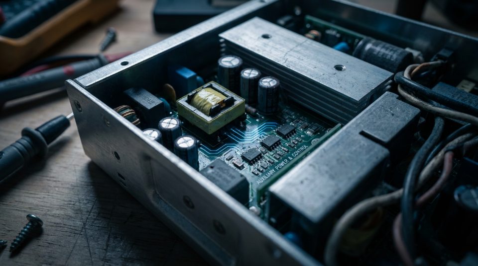
The secret lies in having a dedicated, independent "brain-power" source. In a robust industrial power system, engineers integrate a tiny, separate power converter—specifically, an active PFC flyback converter—to act as an auxiliary power supply. This setup ensures that the internal control circuits always have a rock-steady, independent low-voltage line (usually 5V or 12V) to run on, completely separate from the main power path.
Why the "Brain" Needs Its Own Power Plant
To understand why this is so important, think of an industrial power supply as having two main parts: the "brawn" (the heavy-duty power stages that deliver hundreds of watts to your machinery) and the "brain" (the delicate control chips, microcontrollers, and sensors that monitor voltage, current, and temperature).
If the brain gets its power directly from the main brawny power stage, any sudden change in the main output will affect the brain. For example, if a heavy motor starts up downstream and causes a temporary voltage dip on the main line, the control chips could lose power and reset. This would cause the entire system to crash.
By integrating an active PFC flyback converter as a dedicated auxiliary power supply, you solve this problem completely. This independent converter takes the raw incoming AC power and transforms it into a clean, stable low-voltage rail. Even if the main output is short-circuited, overloaded, or temporarily shut down for safety, the auxiliary supply keeps running. This allows the control chips to:
Keep monitoring system health and logging errors.
Communicate with external controllers or industrial networks (like CAN bus or Modbus) to report what went wrong.
Safely attempt a system reboot once the fault is cleared.
The Magic of the Active PFC Flyback Converter
Why do designers specifically choose an active PFC flyback converter for this job? A flyback converter is a type of voltage-reducing circuit that uses a transformer to store energy and release it. It is highly favored in auxiliary power design for two main reasons: simplicity and isolation.
A flyback transformer physically separates the high-voltage input side from the low-voltage control side. This physical separation, known as galvanic isolation, prevents dangerous high voltages from accidentally jumping over and frying your sensitive control chips.
Furthermore, adding active Power Factor Correction (PFC) to this auxiliary flyback converter ensures that even this small, low-power stage draws current from the grid in a clean, efficient way. According to research on power converter designs published in December 2024, integrating active PFC into the auxiliary flyback stage helps industrial equipment meet strict international harmonic standards (like EN61000-3-2) even when the main, high-power stages of the system are turned off or sitting in standby mode.
Crucial Protection for Gate Drivers and Three-Phase Inverters
This auxiliary power setup is especially crucial in complex industrial systems like three-phase inverters. These inverters are used to control heavy-duty AC motors by rapidly switching high voltages on and off thousands of times per second using powerful electronic switches called MOSFETs or IGBTs.
To turn these giant switches on and off safely, you need specialized chips called gate drivers. Gate drivers are like the muscles that pull the heavy switches. They require sudden, powerful bursts of clean energy to charge up the control gates of the transistors.
If your gate drivers do not get clean, isolated power, several bad things can happen:
Electrical Noise Interference: The rapid switching of high voltages in a three-phase inverter creates massive electromagnetic interference (EMI). If the gate drivers share a power line with the main control chips without isolation, this noise can travel back and corrupt the control signals.
Shoot-Through Failures: If noise corrupts a gate driver's signal, it might accidentally turn on two switches at the same time. This creates a direct short circuit across the high-voltage DC bus—a catastrophic event that usually ends in a loud pop and smoke.
Voltage Fluctuations: When a gate driver demands a quick burst of current, it can pull down the voltage of a poorly designed power line. A dedicated auxiliary supply acts as a buffer, ensuring these sudden demands do not cause voltage dips that affect other sensitive sensors or microcontrollers.
How the Startup Sequence Works
To keep your system safe, a high-quality pfc enclosed power supply uses a carefully timed startup sequence made possible by this auxiliary power integration.
Step 1: The Aux Supply Wakes Up First. When you first apply AC power to the system, the tiny auxiliary flyback converter boots up instantly. It establishes the stable 5V or 12V rails.
Step 2: The Brain Performs Self-Checks. The control chips wake up, powered by the aux supply. They check the system's temperature, input voltage, and overall health before turning on the main power stages.
Step 3: Safe Initialization. Once the brain confirms everything is safe, it sends the signals to start up the main PFC and DC-DC converter stages smoothly.
Step 4: Continuous Monitoring. During operation, if a fault occurs, the main stage can shut down instantly while the aux-powered brain remains awake to safely manage the shutdown and report the status.
Engineering Trade-offs: Dedicated Aux Supply vs. Bias Windings
While a dedicated active PFC auxiliary supply offers maximum reliability, it does come with trade-offs that you must consider when selecting or integrating a power unit.
The Cheap Way (Bias Windings): Some simpler power supplies do not use a separate auxiliary converter. Instead, they wrap an extra loop of wire (a bias winding) around the main power transformer. This is cheap and saves space, but it has a major drawback: if the main power stage shuts down or goes into a low-power standby mode, the bias winding stops producing enough voltage, and the control chips lose power.
The Robust Way (Dedicated Flyback): Using a dedicated auxiliary converter adds more components and slightly increases the initial cost of the unit. However, for industrial environments where downtime can cost thousands of dollars per minute, the ability to keep your control systems alive and communicating during a power fault easily outweighs the minor extra cost.
Key Takeaways
Integrating an active PFC flyback converter as an auxiliary power supply ensures a stable, independent low-voltage rail for internal control circuits.
This auxiliary power setup is crucial in complex systems like three-phase inverters, where control chips and gate drivers require clean, isolated power.
Conclusion
Choosing the right power unit for your industrial setup is about finding the perfect balance for your specific environment. To keep your machinery running without unexpected downtime, you must select a unit that balances active power factor correction, extreme thermal resilience (operating reliably from -40°C to +85°C), and robust transient handling. If your system cannot handle sudden voltage spikes or temperature swings, even the most efficient supply will eventually fail.
Your choice between single-stage and multi-stage PFC architectures comes down to your project's specific constraints:
Choose a single-stage PFC architecture if you are working with limited cabinet space and a tight budget, and your system operates at lower power levels where slight efficiency trade-offs are acceptable.
Opt for a multi-stage PFC architecture if you are running high-power, mission-critical equipment where maximum efficiency, minimal electrical noise, and long-term reliability are your top priorities.
As a next step, evaluate your physical installation conditions. If you are housing your electronics in a sealed, unconditioned outdoor enclosure, look for a high-quality pfc enclosed power supply designed for conduction cooling to prevent overheating. Additionally, calculate your system’s startup demands—if you are running motors or large pumps, ensure your selected unit offers enough peak power overhead to handle those initial startup surges safely. Taking these steps now will save you from costly maintenance and system failures down the road.
FAQ
Why should I choose an enclosed design over an open-frame power supply for industrial cabinets?
Enclosed models feature a metal chassis that protects sensitive components from dust, debris, and accidental contact during installation. This protective casing also acts as an electromagnetic shield, reducing electrical noise that could disrupt nearby control circuits. Open-frame designs are cheaper but leave components vulnerable to harsh factory air.
How does integrating a high-performance pfc enclosed power supply affect OEM system certification?
Using a pre-certified unit simplifies your overall system compliance for safety and electromagnetic compatibility. Because the power supply already manages harmonic distortion and meets strict safety margins, you face a much lower risk of failing final system testing. This pre-compliance can save your engineering team weeks of troubleshooting and expensive redesigns.
Do I need to derate the output power if I mount the unit vertically instead of horizontally?
Yes, mounting orientation directly impacts natural convection cooling through the enclosure vents. Standard horizontal mounting usually allows the best airflow, while vertical mounting can trap heat and require you to derate the output by 10% to 20%. Always check the manufacturer's thermal derating curves to ensure the unit does not overheat in your specific layout.