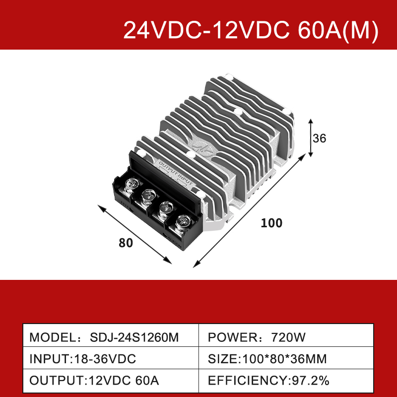
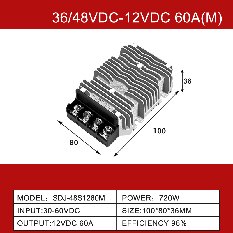
Common ground defines the topology. Input and output share one negative rail, so there is no transformer barrier to lose energy across.
Efficiency above 90% is normal. Because energy moves through an inductor rather than a magnetic barrier, conduction losses stay low at full load.
No barrier means no transient blocking. A switching transistor that fails short can pass the full input voltage to the load.
Buck, boost or buck-boost follows the bus. Step down from 48V or 24V, step up from 12V, and use buck-boost when the battery swings across the target.
Derating decides the real current rating. Read the curve at your cabinet ambient, not the headline amperage on the front page.
Ground loops are the hidden cost. Shared returns between cabinets carry stray current, so plan single-point grounding before adding modules.
Introduction
A non isolated dc dc converter is a highly efficient power management device that shares a common ground between its input and output terminals. Unlike their isolated counterparts, these converters do not utilize a high-frequency transformer, which significantly reduces their physical footprint and manufacturing complexity. By relying on inductive energy storage and rapid switching mechanisms, they provide precise voltage regulation for applications where a galvanic barrier is not strictly required by safety or noise-reduction standards. They are heavily utilized in telecom infrastructure, automotive systems, and distributed power architectures. Inside a sealed cabinet, a 12V/24V to 5V waterproof buck module is often the first stage behind that decision.
Common Ground vs. Non-Isolated Constraints: Key Differences
When engineering a power distribution network, understanding the implications of a common ground architecture in a non-isolated dc-dc converter is essential for avoiding catastrophic system failures.
The Principle of a Common Ground
In a non-isolated architecture, the negative terminal (ground) of the input voltage source is directly connected to the negative terminal of the output load. This continuous electrical path simplifies the circuit design and eliminates the energy losses associated with magnetic transfer across a transformer. The result is a highly efficient power transfer, often exceeding 95% efficiency. However, this shared reference point means that any ground noise or voltage fluctuations on the input bus will be directly coupled to the output circuitry.
Limitations and Safety Constraints
Because there is no galvanic isolation barrier, non-isolated converters cannot protect sensitive downstream microprocessors from severe high-voltage input transients or fault conditions. If the primary switching transistor fails in a short-circuit state, the entire input voltage may be dumped directly onto the output load, potentially destroying connected devices. Therefore, these converters are primarily deployed in environments where the primary power source is already isolated from the AC mains and relatively stable.
Ground Loop Vulnerabilities
A significant constraint of a shared ground is the potential for ground loops. When multiple devices are connected to different ground points with varying potentials, unintended currents can flow through the ground return path. This introduces electromagnetic interference (EMI) and signal distortion. Engineers must employ careful PCB layout techniques and single-point grounding strategies to mitigate these issues when deploying non-isolated modules.
Table 1: Common Ground vs Galvanic Isolation in 12V/24V/48V Systems
Attribute
Non-isolated (common ground)
Isolated (transformer barrier)
Input transient
Passed to the load if the switch fails short
Blocked by the transformer
Efficiency band
Often above 90% at full load
Lower, with added winding losses
Footprint and cost
Smaller board area, lower cost
Larger, with a heavier magnetic
Ground loops
Possible between separate ground points
Broken at the barrier
Typical fit
Bus step-down inside one enclosure
Cross-cabinet or contact-linked loads
Buck, Boost, and Buck-Boost: Choosing the Right 12V/24V/48V Step
The core functionality of non-isolated dc-dc converters relies on specific switching topologies to manipulate the voltage levels across 12V, 24V, and 48V industrial DC buses.
Step-Down (Buck) Converters
The buck converter is designed exclusively to step down an input voltage to a lower output voltage. For instance, converting a 24V industrial bus down to a stable 12V or 5V to power logic controllers. It utilizes a switching transistor, a diode (or synchronous rectifier), an inductor, and a capacitor. Because it draws current in pulses but delivers a continuous current through the inductor, it is highly efficient and generates minimal output voltage ripple, making it ideal for powering sensitive microcontrollers.
Step-Up (Boost) Converters
Conversely, the boost converter steps up a lower input voltage to a higher output voltage. This is critical in applications where a 12V battery system must power a 24V or 48V sensor network or actuator array. The boost topology stores energy in the inductor during the switch's on-time and subsequently discharges it, along with the input voltage, to the load during the off-time. Due to the discontinuous nature of the output current, boost converters generally require larger output capacitors to smooth the voltage ripple.
Buck-Boost Regulators
A buck-boost converter provides the ultimate flexibility by maintaining a regulated output voltage regardless of whether the input voltage fluctuates above or below the target output. This is particularly vital in battery-powered systems where the battery voltage starts high when fully charged (e.g., 14V) but drops significantly as it discharges (e.g., 9V). If the required output is a steady 12V, the buck-boost topology seamlessly transitions from bucking the voltage to boosting it, ensuring uninterrupted operation of the connected load.
Table 2: Buck, Boost and Buck-Boost Compared for 12V/24V/48V Buses
Criterion
Buck (step-down)
Boost (step-up)
Buck-boost
Output against input
Always lower
Always higher
Either side of input
Inductor current
Continuous
Discontinuous at the output
Continuous, with a mode change
Output ripple
Lowest
Higher, needs larger capacitors
Moderate
Bus example
48V or 24V down to 12V
12V up to 24V or 48V
12V battery held at 12V
Control complexity
Lowest
Moderate
Highest
For a 24V rail feeding 12V logic, a 24V to 12V step-down unit rated 1.5A to 100A covers the whole current span without changing topology, while a 48V bus uses the same circuit with a different turns ratio.
How to Select Non-Isolated Modules for Industrial Buses
Integrating a non isolated dc dc power module into a rugged industrial environment requires a meticulous evaluation of electrical and mechanical parameters beyond basic voltage conversion.
Evaluating Efficiency Curves
Efficiency is not a static number; it varies dynamically with the input voltage and the load current. When selecting a module, scrutinize the efficiency curves provided in the datasheet. A high-quality converter should maintain an efficiency above 90% across a broad load range, typically from 20% to 100% of maximum capacity. Poor efficiency at light loads can lead to unacceptable thermal dissipation in systems that spend long periods in standby modes.
Thermal Management and Ambient Temperature
Because they are extremely compact, non-isolated converters have high power densities, making thermal management critical. Determine the maximum ambient temperature of the installation environment (e.g., inside an unventilated control cabinet) and consult the module's thermal derating curve. Ensure the converter can deliver the required continuous current without exceeding its maximum safe operating junction temperature, which often necessitates potting or external heat sinking.
Dynamic Load Response
Industrial loads, such as solenoids, motors, or high-speed relays, often exhibit sudden spikes in current demand. The converter's dynamic load response (or transient response) dictates how quickly the output voltage recovers from a sudden load step without significant overshoot or undershoot. Fast transient response is critical to prevent logic resets or erratic behavior in PLCs and automation controllers sharing the same power bus.
Deploying a non isolated dc dc converter is an effective strategy for achieving high-efficiency voltage regulation within established, low-voltage power architectures. By understanding the constraints of a common ground, selecting the appropriate buck or boost topology, and rigorously evaluating thermal and dynamic load parameters, engineers can design robust 12V, 24V, and 48V distribution networks.
The next step is to measure rather than assume: log the bus voltage at the module terminals under load, record the cabinet ambient at the hottest hour, and note the largest load step the rail will see. Compare each figure against the derating curve and the transient response plot before a part is committed to the BOM.
Q: What is a non isolated dc dc converter used for?
A: It converts one DC bus level to another while keeping a shared negative rail, so it suits step-down and step-up duties inside equipment that already has an isolated front end. Typical uses are 48V to 12V logic rails, 12V to 24V actuator supplies and battery-backed instrumentation.
Q: When should I choose an isolated converter instead?
A: Choose isolation when the load touches a person, when two grounded cabinets must be joined, or when the input can carry large transients that must not reach the output. A non-isolated module passes a shorted switch straight through, so the barrier is what limits fault energy.
Q: Can a 12V battery run a 24V load with a non-isolated module?
A: Yes, with a boost topology. A 12V to 24V step-up stage takes the battery rail upward and holds regulation as the battery falls, though input current rises in proportion to the step-up ratio, so the feed wiring must be sized for that higher current.
Q: Why does efficiency fall at light load?
A: Switching and core losses stay roughly fixed while output power drops, so the ratio worsens at 10% to 20% load. Systems that idle for long periods should be checked on the efficiency curve near their standby current, not only at full rated output.
Q: How do I avoid ground loops between two cabinets?
A: Feed each cabinet from its own converter and keep a single bonding point, so no return current shares a path with signal ground. Where two grounds must meet, an IP68 boost-buck module for 13.8V rails with a floating output side removes the loop entirely.